TECHNICAL GUIDES · LED FOG LIGHTS
Thermal Management and Driver Circuitry in High-Power LED Fog Lamp Assemblies
A practical engineering guide for automotive lighting buyers, importers, and OEM/ODM program managers.
October 28, 2026 · 12 min read
Introduction
Compact LED fog lamps must deliver controlled optical output while operating in crowded bumper cavities exposed to summer heat, road spray, dust, and limited airflow. Higher electrical input does not automatically translate into higher sustained on-road brightness: the LED package, printed circuit board, thermal interface, housing, and driver have to work as one system.
Poor heat transfer can raise LED junction temperature, accelerate light-output depreciation, shift color, stress solder connections, and shorten the life of electronics. Meanwhile, an overly aggressive constant-current setting may produce impressive initial readings but trigger current reduction once the assembled lamp reaches thermal equilibrium.
This guide explains the engineering decisions behind LED fog light thermal management, compares direct-thermal-path (DTP) copper substrates with aluminum metal-core PCBs, and examines die-cast housings and temperature-aware driver circuitry. For distributors and private-label buyers, the objective is not a single impressive material specification; it is repeatable photometric and electrical performance in the finished fog-lamp assembly.
Table of Contents
Quick Guide: LED Fog Light Thermal & Driver Engineering
QUICK GUIDE
01
Thermal Resistance and Degradation
Trace the complete junction-to-ambient heat path.
02
DTP Copper vs Aluminum MCPCB
Compare board stack-ups under matched conditions.
03
ADC12 Housing and Passive Cooling
Review TIM, fin geometry, and installed airflow.
04
Constant-Current and NTC Foldback
Verify sensor placement, derating, and recovery.
Connect supplier claims to documented test evidence.
1. Thermal Resistance: Why Small Fog Lamps Run Hot
An LED does not dispose of all its electrical input as visible light. The heat generated depends on the LED package, operating point, and optical efficiency; a single universal “70% heat” assumption is not suitable for calculating a real product. Engineers instead establish the thermal power and resistance chain for the selected emitter and operating conditions.
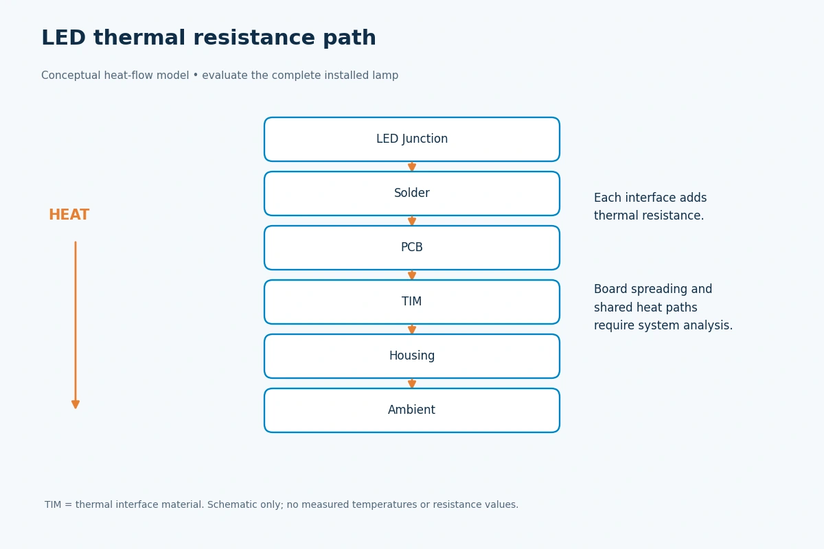
The useful design model is a heat path from LED junction to package solder point, board substrate, thermal interface material (TIM), housing, and surrounding air. Each interface adds thermal resistance. In a simplified steady-state case, the junction temperature rise is related to dissipated heat multiplied by the relevant junction-to-ambient thermal resistance. Multi-emitter boards require careful treatment of shared thermal paths and heat spreading.
A hot bumper cavity is not equivalent to laboratory ambient air. The design must be assessed with the complete lamp mounted as intended, including surrounding trim, seals, brackets, cable routing, and potential mud accumulation.
What elevated temperature can change
Luminous flux and color: optical output can fall temporarily with temperature, while long exposure can contribute to irreversible lumen and color maintenance changes. The effect depends on the emitter and materials.
Solder and interface fatigue: repeated thermal cycling can stress solder joints, adhesive bonds, and dissimilar-metal interfaces. Good contact pressure and stable TIM application matter as much as substrate choice.
Driver and passive components: electrolytic capacitors, switching devices, and other components may have shorter service life at higher temperatures. Heat must be evaluated at the driver board, not only at the LEDs.
Engineering takeaway: obtain the LED datasheet’s thermal limits and temperature-measurement method, measure accessible board and case temperatures at thermal equilibrium, and estimate junction temperature using the manufacturer’s validated approach. There is no universal 85°C or 105°C threshold for every fog-lamp design.
2. DTP Copper PCBs vs. Aluminum MCPCBs
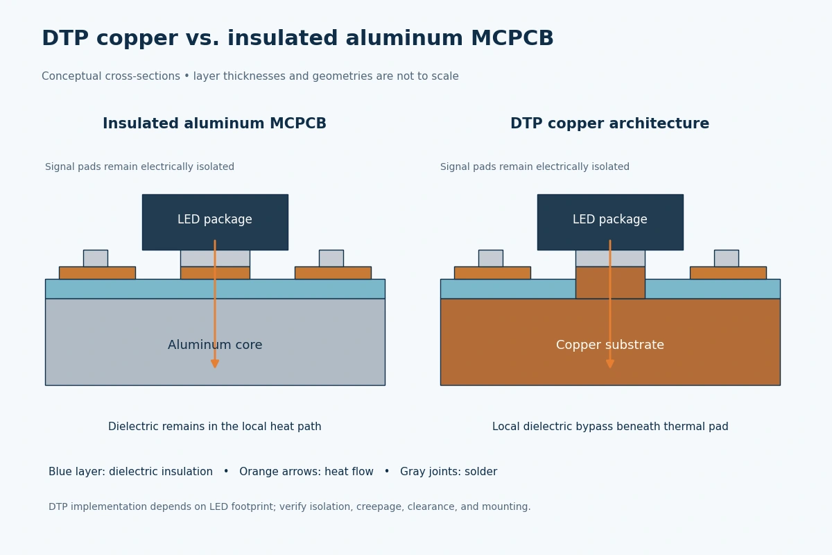
Many LED fog lamps use insulated metal-substrate circuit boards. An aluminum MCPCB typically places a dielectric layer between the copper circuitry and the metal core. That dielectric provides electrical insulation but adds thermal resistance. Its thickness, thermal conductivity, and actual heat-flow area can materially influence performance.
A DTP design creates a dedicated thermally conductive route beneath an LED thermal pad, reducing or bypassing a localized dielectric bottleneck while retaining the electrical isolation required elsewhere by the circuit design. Implementations vary by board vendor and LED footprint. DTP is not a universal substitute for reviewing creepage, clearance, manufacturability, solder attachment, and thermal interfaces.
Engineering comparison: evaluate the assembly, not just metal conductivity
| Design question | Insulated aluminum MCPCB | DTP copper architecture |
|---|---|---|
| Heat path beneath LED | Usually includes engineered dielectric in the junction-to-core path | Dedicated low-resistance thermal route may bypass a local dielectric barrier |
| Electrical isolation | Established by dielectric system; verify breakdown and insulation specifications | Must be demonstrated for the complete PCB layout and mounting scheme |
| Lateral heat spreading | Dependent on copper layers, core, thickness, and geometry | Dependent on copper thickness, contact geometry, and board layout |
| Cost and manufacturing | Often attractive for cost-sensitive volume production | May require more specialized fabrication and process controls |
| Best verification | Rth measurements, LED temperature, electrical and dielectric tests | Same assembled-lamp tests; do not infer performance from copper bulk conductivity |
Bulk copper has higher thermal conductivity than many aluminum alloys, but that fact alone does not prove a DTP board halves LED temperature or doubles system-level cooling. Thermal resistance depends on the full geometry and all interfaces. In some power ranges, a well-designed aluminum MCPCB may satisfy the thermal budget with better cost and supply availability.
For purchasing decisions, request a cross-section drawing, substrate stack-up, dielectric specifications where applicable, a board-level thermal comparison under matched electrical power, and a consistent test fixture. Treat vendor figures for junction temperature and power density as model-specific results, not universal claims.
3. ADC12 Die-Cast Housings and Passive Heat Rejection
After heat reaches the back of the LED substrate, it must pass through the TIM and into the enclosure. Die-cast aluminum alloys such as ADC12 can provide a useful combination of casting detail, structural strength, and heat conduction, but their thermal properties depend on composition, processing, and design. A statement such as “ADC12 always conducts at exactly 120 W/m·K” is too specific without a material certificate or datasheet.
Casting fins help by increasing exposed surface area; however, deep fins do not automatically outperform shorter ones inside a crowded bumper. Airflow clearance, fin spacing, mounting orientation, road dirt, and interaction with surrounding plastic can reduce the benefit. Designers should evaluate both still-air and realistic vehicle-cavity conditions.
Three practical design controls
Thermal interface quality — Specify the TIM type, contact coverage, assembly pressure, mounting flatness, and long-term pump-out or drying resistance. An oversized heat sink cannot fully compensate for a poor board-to-housing interface.
Housing and fin geometry — Balance passive convection, heat spreading, sealing interfaces, casting tolerance, weight, and corrosion management. Avoid creating pockets that trap mud or water around fins.
Sealing and pressure management — Water resistance and heat rejection are separate engineering questions. Validate the chosen enclosure design and any pressure-equalization vent under its intended environmental exposure, rather than assuming a sealed housing has no thermal trade-offs.
For a production approval, request temperature measurements at the LED board, near the driver’s hottest components, and on the housing after a specified stabilization period. Record ambient temperature, mounting condition, supply voltage, input power, LED drive current, and optical output so that tests are repeatable between factories and batches.
4. Constant-Current Drivers and NTC Thermal Foldback
An automotive LED driver must maintain controlled LED current over the specified vehicle supply range, while protecting the system against relevant electrical disturbances. Constant-current regulation is necessary because LED current can change significantly with voltage and temperature. The acceptable input-voltage range and transient protections depend on the specific vehicle and product specification; they should not be assumed to be 9–36 V for every fog lamp.
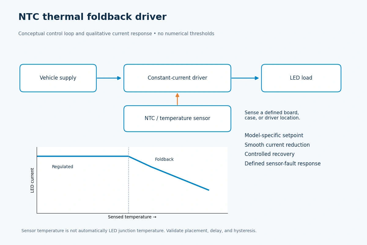
Thermal foldback adds a protection loop. A thermistor or temperature sensor monitors an appropriate board, case, or driver location. As a calibrated threshold is approached, the driver can progressively reduce LED current to limit further heating. A good design avoids flicker and abrupt oscillation, while preserving a documented minimum output and allowing recovery as the device cools.
What to examine in a temperature-current curve
Nominal region — At acceptable measured temperature, the driver maintains its designated regulated current within tolerance.
Derating region — Above a model-specific setpoint, current is reduced smoothly in accordance with an intentional curve, with suitable filtering or hysteresis.
Recovery and fault response — Once temperature falls, current recovers in a controlled way; open/short LED and sensor-failure behavior is defined and tested.
The NTC’s placement matters. A sensor measuring the driver PCB may not represent LED junction temperature, and a poorly attached sensor can respond too slowly to a local hotspot. Suppliers should provide the sense location, NTC or sensor characteristics, foldback setpoint, curve, and worst-case measurement uncertainty.
LED drivers can also generate conducted and radiated electromagnetic emissions. CISPR 25 provides test methods and limits for disturbances that affect onboard receivers, but it should not be presented as a blanket guarantee against all electrical interference. Buyers should request the appropriate test version, configuration, limits, and report for the particular lamp and vehicle application.
5. B2B Sourcing Checklist: Evidence Before Production Approval
For OEM replacements, distributors, and private-label programs, a strong supplier review connects engineering decisions to testable documents. The same nominal wattage or LED brand can produce very different steady-state output, thermal margin, and warranty behavior when boards, housings, and drivers differ.
- Confirm the exact LED package, operating current, rated temperature limits, and temperature-measurement point.
- Request the PCB stack-up and, for DTP designs, a clear drawing of the direct thermal route and isolation scheme.
- Record TIM material, process controls, contact pressure, and housing alloy specification.
- Evaluate in-situ board, driver, and housing temperatures in the complete mounted fog lamp.
- Obtain stabilized photometric output and input power across agreed ambient temperatures and supply-voltage conditions.
- Review driver current-vs-temperature behavior, NTC location, fault response, and thermal recovery.
- Request automotive electrical and EMC reports applicable to the target product and market, including CISPR 25 where specified.
- Review LED-level LM-80/TM-21 data where available, but require assembly-level durability evidence before stating whole-lamp lifetime.
Suggested supplier validation matrix
| Test / evidence | Why it matters | Required reporting detail |
|---|---|---|
| Thermal equilibrium test | Shows real installed temperature margin | Mounting, ambient, voltage, power, Ts/Tc, stabilization |
| Photometric hot/cold comparison | Shows sustained useful light output | Initial vs stabilized flux/intensity and beam behavior |
| Current-temperature sweep | Confirms intentional foldback and recovery | Sensor position, current curve, thresholds, hysteresis |
| PCB and TIM process records | Tests consistency of the thermal interface | Stack-up, material lot, coverage and inspection method |
| Thermal cycling / environmental tests | Screens mechanical and sealing weaknesses | Agreed cycles, conditions, acceptance criteria |
| EMC and input transients | Evaluates vehicle electrical compatibility | Applicable standard edition, setup, result, exceptions |
Avoid an unsupported requirement such as “every product must pass 1,000 hours at -40°C to +85°C with less than 5% loss.” A valid acceptance plan defines the test profile and duration, sample size, baseline measurement, measurement uncertainty, and agreed pass/fail limits for the particular program.
Frequently Asked Questions
Q1. Why is LED fog light thermal management difficult in a sealed bumper housing?
The housing offers limited exposed surface area, often sits near warm vehicle structures, and may experience dirt or water accumulation. Heat must escape through the LED package, PCB, TIM, and enclosure into the surrounding environment. Testing the complete installed assembly is more informative than judging the heat sink in open air.
Q2. Does a DTP copper PCB always outperform an aluminum MCPCB?
No. DTP can reduce a localized thermal bottleneck under the LED pad, but performance depends on the LED footprint, geometry, electrical isolation, TIM, housing, and power. Compare measured thermal resistance and junction-temperature estimates under matched conditions, not copper conductivity alone.
Q3. What does NTC thermal foldback do in a fog-lamp driver?
A temperature sensor helps the driver limit LED current when a specified local temperature is reached. This can protect components from overheating, but the setpoint, ramp, output reduction, and recovery behavior must be designed and validated for that particular assembly.
Q4. Why might a fog light get dimmer after it has been on for some time?
As the assembled light warms, LED efficiency can decline and some drivers intentionally reduce current through thermal foldback. A stabilized output test that records LED current and temperature helps distinguish normal temperature behavior from excessive thermal restriction or an electrical fault.
Q5. Are passive die-cast housings always better than fans?
Neither architecture is automatically superior. Many compact, weather-exposed fog lamps favor passive cooling because it avoids moving parts and simplifies sealing, but suitability depends on package size, heat load, vehicle location, service requirements, and validated environmental performance.
Q6. What evidence should NVEL B2B buyers request before ordering a thermal-optimized fog light?
Request model-specific electrical and optical specifications, PCB and housing drawings, thermal test conditions and results, driver derating curves, environmental and EMC reports where applicable, and a documented sample approval plan. NVEL can discuss these requirements with buyers and coordinate review of the documents actually available for the selected product; certification or manufacturing-process claims must be supported separately.
Conclusion
Reliable high-power fog lighting depends on coordinated thermal and electrical design, not one headline material. DTP copper substrates can improve a local heat path, aluminum MCPCBs remain useful where the thermal budget allows, and ADC12-style die-cast housings must be evaluated with their actual geometry and surroundings. Constant-current regulation and temperature-aware foldback then help define how the assembly behaves throughout a demanding operating cycle.
For B2B buyers, the most useful specification is a repeatable result: stable light output, measured thermal margin, documented electrical protection, and traceable production controls. Use the qualification matrix in this guide to compare proposals on evidence rather than unverified wattage, conductivity, or lifetime claims.
Explore NVEL Automotive Lighting Solutions
Planning a new fog-lamp range or reviewing an existing supplier? Compare product options and request model-specific technical documentation from NVEL.
Related Technical Guides
Technical Guides · LED Fog Lights
SAE J583 & ECE R19 Fog Lamp Compliance: Optical Cutoff and Wide-Beam Dispersion
Technical Guides · LED Fog Lights