TECHNICAL GUIDES · LED OFF-ROAD LIGHTS
Extreme Durability in Heavy Duty LED Work Light: Thermal Shock, Vibration, and MIL-STD-810G Compliance
Evaluate vibration, mechanical shock, thermal cycling and model-specific durability evidence.
October 27, 2026 · 15 min read
Introduction
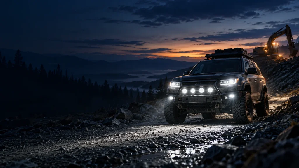
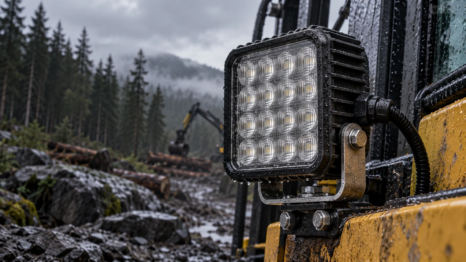
Auxiliary LED work lights on excavators, agricultural tractors, forestry machines, off-road trucks and other heavy-duty vehicles face more than ordinary road vibration. Engine excitation, uneven terrain, repeated impacts, rapid temperature changes and contaminated wash water can act on the same luminaire throughout its service life. A lamp that performs well during a short bench test may behave differently after thousands of operating hours in these environments.
Potential failure modes include solder-joint fatigue, loose connectors, bracket cracking, beam misalignment, lens or gasket movement and moisture ingress. Their importance depends on mounting location, duty cycle, the vehicle vibration spectrum and the complete lamp assembly. No single failure mode should be described as the universal primary cause of field returns without service data.
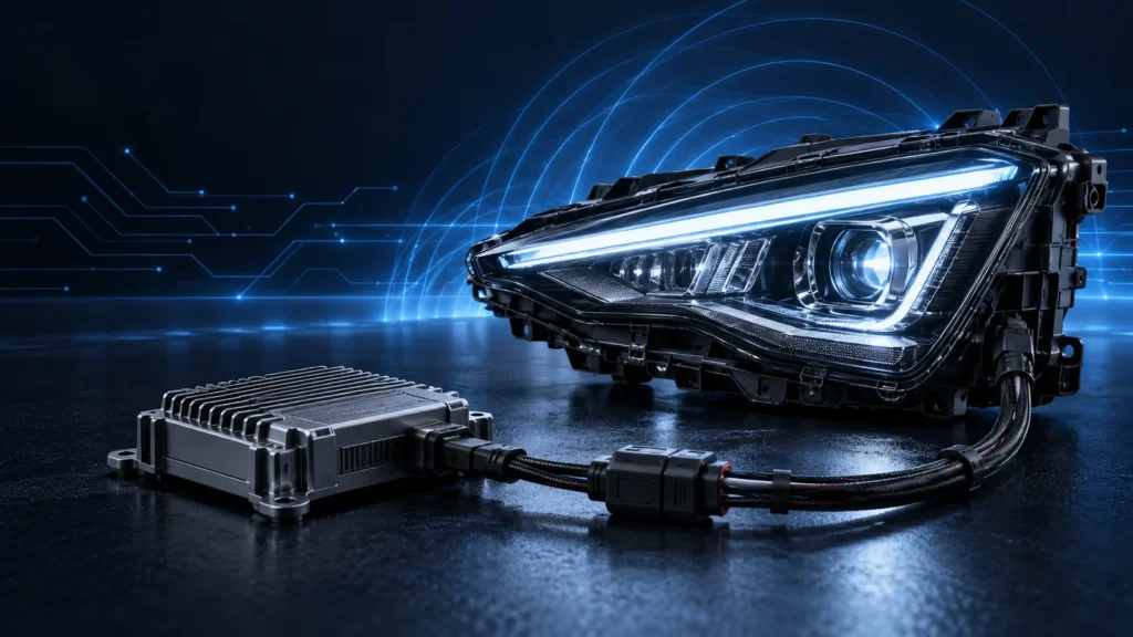
For OEM/ODM buyers and aftermarket distributors, a heavy duty LED work light vibration test is only one part of a credible durability program. Component selection, housing stiffness, PCB support, potting strategy, shock profiles, climatic testing and production consistency must be assessed together. This guide explains the engineering decisions behind rugged off-road lighting—and how to request evidence that supports supplier claims.
Table of Contents
Heavy-Duty Shock and Vibration Engineering
QUICK GUIDE
1. Structural Fatigue and Vibration in Off-Road LED Lighting
1.1 Why the vibration spectrum matters
Machine vibrations are not defined by one frequency or one acceleration value. Rotating equipment may create narrowband excitation, while road irregularities and machine operation produce broadband, sometimes random, vibration. A component’s response depends on input direction, frequency content, duration and the mechanical resonance of the mounted assembly.
At a resonant frequency, a poorly supported PCB, bracket or optical assembly can experience amplified movement even when the vehicle input seems moderate. Fatigue damage depends on repeated strain cycles and material properties, not just the peak acceleration printed on a specification sheet.
1.2 Common mechanical failure pathways
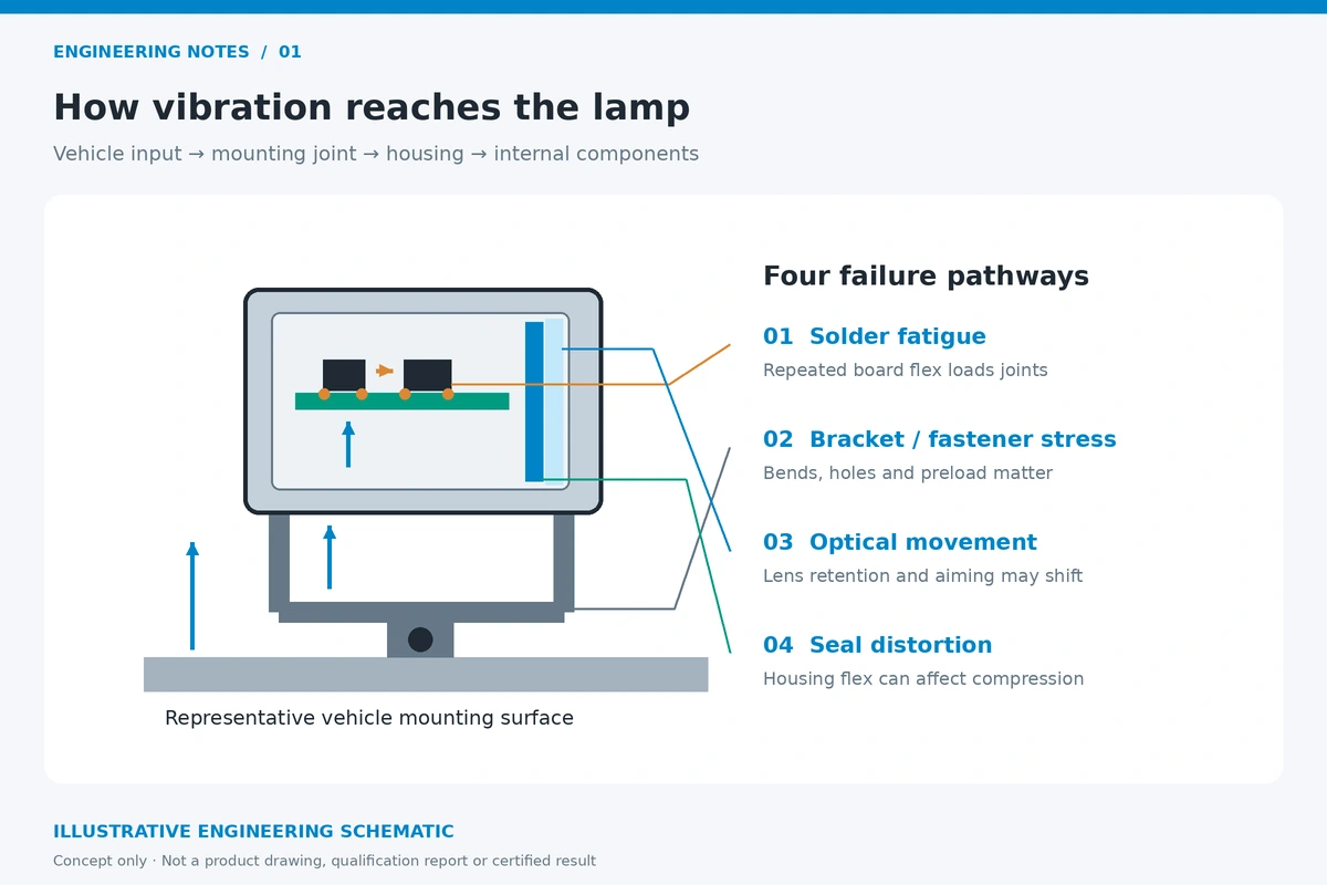
Solder joints and electronic components: cyclic board flex may fatigue solder connections, heavy components or connector interfaces, potentially producing intermittent operation.
Brackets and fasteners: high local stress at slots, bends, welds and mounting holes may cause loosening, plastic deformation or fatigue cracks.
Optical alignment: movement of the lens, reflector or LED board can change aiming, beam shape and glare characteristics.
Seal interfaces: repeated housing distortion or loss of gasket compression can increase the risk of water or dust ingress.
Engineering teams should therefore inspect the complete assembly in its intended orientation, with representative mounting hardware and cable routing. A stronger bracket alone cannot compensate for a fragile PCB, an unsuitable fastener or inadequate enclosure support.
2. PCB Potting, Housing Materials and Mounting Design
2.1 Potting is a design option—not a universal requirement
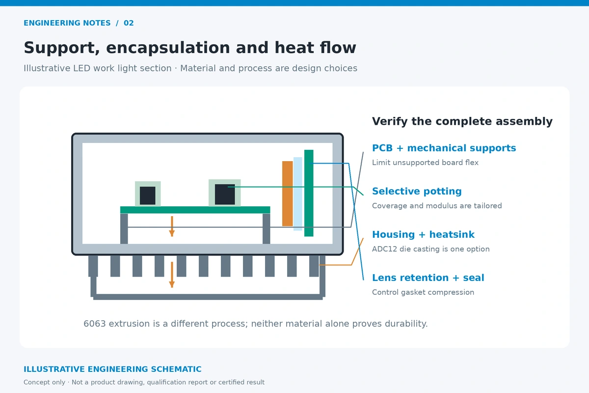
Silicone, polyurethane and epoxy-based encapsulants can help restrain components and protect selected electronic assemblies against moisture or vibration. Their mechanical stiffness, thermal conductivity, expansion behavior, adhesion and serviceability differ. Excessive stiffness or incompatible thermal expansion may transfer stress to solder joints rather than eliminate it.
Full-chamber potting is not inherently superior to a properly engineered combination of board supports, selective potting, conformal coating and sealed connectors. When a supplier specifies 100% silicone potting, buyers should verify which cavity is filled, the material designation, cure process, thermal path, rework strategy and representative qualification data.
2.2 ADC12 die-cast housings, extruded aluminum and thermal paths
ADC12 is commonly associated with aluminum die-casting, while 6063 is often used for extruded aluminum profiles; these should not be combined into the unsupported phrase “6063 die-casting” as if the processes were interchangeable. Both material and manufacturing process matter, but reliability also depends on wall geometry, porosity control, surface finish, fastener bosses, corrosion protection and the LED-to-housing thermal interface.
An enclosure must provide mechanical stiffness while conducting heat away from sensitive electronics and LED junctions. A thicker casting is not automatically cooler, lighter or more fatigue-resistant; the entire design must be assessed.
2.3 Stainless-steel brackets and fastening practice
304 and 316 stainless steel can be useful where corrosion resistance matters, but the optimum bracket grade and thickness depend on loads, geometry and fatigue testing. A 3–5 mm bracket is a possible design choice, not a universal pass/fail requirement. Mounting hardware should be specified by the appropriate property class or stainless fastener designation, not described as “Grade 8.8 stainless steel” without qualification: ISO property class 8.8 conventionally describes carbon/alloy steel fasteners, whereas stainless fasteners use different classifications.
Joint design should address preload, loosening resistance, fatigue at bend radii, galvanic contact, cable strain relief and service access. Validate the intended bracket and mounting location, not merely the nominal material thickness.
Engineering Comparison: Options and Buyer Verification
| Component | Engineering choices | What B2B buyers should verify |
|---|---|---|
| PCB stabilization | Selective or full potting; compliant coating; mechanical supports | Material datasheet, cure records, coverage area, vibration results |
| Housing | ADC12 die casting; 6063 extrusion where appropriate; other qualified alloys | Alloy/process, casting defects, sealing surfaces, thermal data |
| Bracket | Formed stainless steel or engineered aluminum / steel mount | Thickness and geometry, fatigue performance, fastening method |
| Fasteners | Properly specified carbon-steel or stainless grades | Corrosion, torque/preload specification, loosening tests |
| Lens and gasket | Mechanical retention, designed seal compression, suitable elastomer | Assembly drawing, IP reports, thermal-cycle inspection |
A higher-cost material or more extensive potting may be justified in some applications, but should be selected against a documented requirement rather than marketed as proof of durability by itself.
3. MIL-STD-810G, ISO 16750-3 and Mechanical Shock Test Planning
3.1 What MIL-STD-810G does—and does not—mean
MIL-STD-810G provides environmental engineering guidance and laboratory methods, including Method 514.6 for vibration and Method 516.6 for shock. It is not a blanket product certification program and does not prescribe one universally applicable vibration or shock profile. The test procedure, exposure, axis, mounting method, operating condition and acceptance criteria must be tailored to the real service environment.
A supplier statement such as “MIL-STD-810G compliant” is incomplete unless it identifies the applicable method and procedure, test severity, duration, sample configuration, results and tested product version. A report for a separate lamp model should not be represented as evidence for the model being purchased.
3.2 Vehicle-oriented alternatives and complementary references
ISO 16750-3:2023 addresses mechanical loads for applicable electrical and electronic vehicle systems and components, with test choices related to mounting locations. SAE J1455 addresses environmental practices for electronic equipment in heavy-duty vehicle applications, including trucks, construction and agricultural machinery. Engineers should select an appropriate standard and an application-specific profile rather than mechanically mixing ranges and durations from different publications.
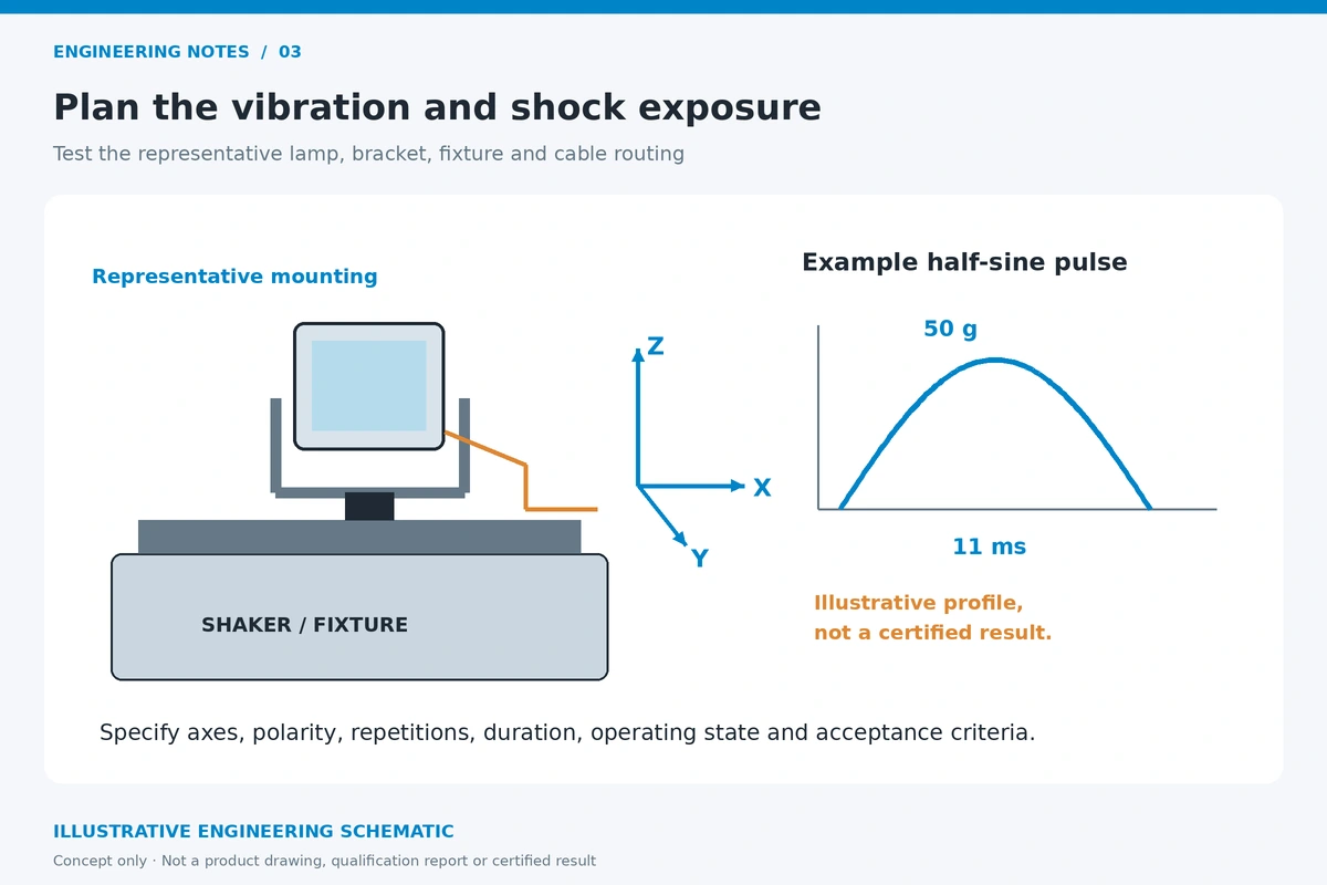
3.3 Interpreting a 50 g half-sine shock example
A “50 g, 11 ms half-sine, three-axis” pulse may be a useful proposed shock test condition, but it is not an automatic requirement of every MIL-STD-810G or ISO 16750-3 program. Its adequacy depends on pulse polarity, number of shocks, mounting arrangement, operating state and what the assembly must still do afterwards.
Peak acceleration by itself cannot prove resistance to vehicle rollover, rock strikes or every field accident. A 50 g laboratory pulse represents only the defined acceleration-time exposure of that test, not a guarantee against unbounded impact damage.
3.4 Representative validation matrix
| Test family | Example reference | Required test-report detail |
|---|---|---|
| Vibration | MIL-STD-810G Method 514.6; ISO 16750-3; SAE J1455 | PSD or sweep definition, axes, exposure, fixture, functional monitoring |
| Mechanical shock | MIL-STD-810G Method 516.6 or agreed vehicle profile | Pulse shape, g level, duration, repetitions, axes, pass criteria |
| External impact | IEC 62262 (IK code) where appropriate | Enclosure/impact surface tested, impact energy, acceptance criteria |
| Climatic loading | ISO 16750-4 where applicable | Temperature cycles, dwell times, ramp rates, operating state |
| Ingress protection | ISO 20653 for road-vehicle enclosures | Exact IP designation, whole-unit test boundary and conditions |
| EMC / radiated emissions | CISPR 25, chosen edition/class for target program | Test setup, frequency limits, report for relevant operating modes |
The IK classification refers to resistance of the tested enclosure to external mechanical impact under defined conditions. It should not be used as an unconditional claim that a lamp lens is immune to any road debris or stone impact.
4. Thermal Shock, Pressure Equalization and Environmental Sealing
4.1 Differential thermal expansion and seal performance
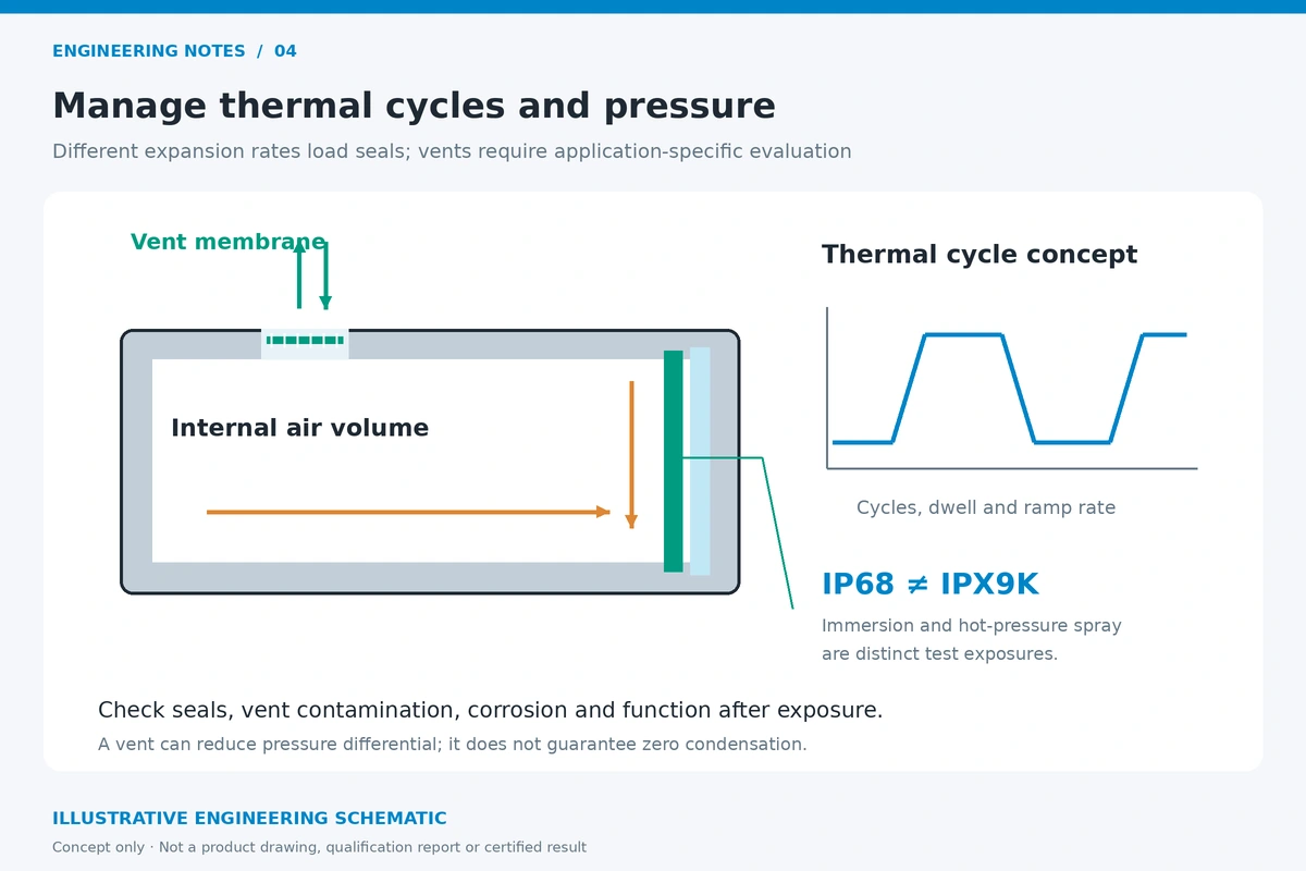
Off-road lighting may move rapidly between hot operating conditions, cold ambient air, splashing water and washdown environments. Aluminum housings, polymer optics, adhesives and elastomeric seals expand and contract at different rates. Repeated temperature changes can affect compression, bonding and joint alignment, especially where the enclosure has little allowance for movement.
A proposed -40°C to +105°C qualification envelope should be treated as an application-specific test target, not as an NVEL product guarantee. The relevant climatic profile, electrical operating mode and acceptance criteria should be documented. Product survival should include post-exposure functional and sealing checks.
4.2 Vent membranes: helpful but not magic
A correctly selected hydrophobic vent can help equalize enclosure pressure as temperature and altitude change. It may reduce pressure differential across seals, but it does not guarantee zero condensation, permanent waterproofing or unrestricted high-pressure washdown resistance. Vent type, placement, contamination and service life require evaluation.
4.3 IP68 and IPX9K are distinct test claims
IP68 indicates specific dust and immersion protection conditions for a tested enclosure; the immersion conditions must be specified. High-temperature, high-pressure water spray is a different exposure. For road-vehicle equipment, ISO 20653 includes special “K” designations such as IPX9K. An IP68 claim does not automatically imply IPX9K performance, and vice versa.
Buyers should confirm whether the test applies to the complete lamp, an external driver, the connector or only a subassembly. Genuine durability evidence identifies the full tested configuration and its acceptance criteria.
4.4 Corrosion and coastal use
Marine or salt-exposed applications may require corrosion-resistant coatings, suitable stainless fasteners, controlled galvanic couples and salt-spray or cyclic-corrosion testing. Neither ADC12, 316 stainless steel nor powder coating alone ensures a specified service life in saltwater. Specific material combinations and protective finishes should be validated for the intended installation.
5. B2B Sourcing Checklist for Rugged LED Work Lights
Use the following checks during RFQ review, sample approval and production qualification. Each item should be supported by a controlled drawing, test report, sample or documented process where applicable.
- Define the duty cycle, mounting location, operating voltage and expected vibration spectrum before choosing a test profile.
- Request product-specific multi-axis vibration and shock reports, including sample ID, fixture, axes, duration and acceptance criteria.
- Evaluate PCB support and potting coverage; request encapsulant type, processing records and thermal consequences.
- Review housing alloy, forming or casting process, coating specification and critical sealing dimensions.
- Check bracket geometry, hardware property designation, torque/preload method and vibration loosening performance.
- Verify beam aiming and optical retention after mechanical and climatic testing.
- Confirm IP test boundaries and distinguish immersion claims from high-pressure washdown claims.
- Require environmental cycling or thermal shock data appropriate to the intended use environment.
- Request an appropriate EMC report (for example CISPR 25) where vehicle electronics compatibility is relevant.
- Verify corrosion, salt-spray or cyclic-corrosion tests if the product will be used on coastal or winter-service vehicles.
- Approve representative production samples and document lot traceability, change control and warranty feedback procedures.
- Confirm market-specific installation and road-use requirements; mechanical durability does not establish lighting approval.
Procurement priority: compare test conditions and evidence against the application, not solely against marketing labels such as “military grade,” “50G approved,” “IP69K certified” or “100% waterproof.”
Frequently Asked Questions
Q1. What is PCB potting, and does every off-road work light need it?
Potting places a protective encapsulant around selected electronic components or within a defined enclosure cavity. It can improve mechanical support and environmental protection when correctly selected and processed. Full potting is not mandatory for every design; mechanical supports, coating, sealing and serviceability may offer a better balance. Test data should demonstrate that the chosen approach works.
Q2. What is the difference between IP68 and IP69K?
IP68 covers defined dust and immersion conditions, whereas IPX9K under ISO 20653 addresses a different high-pressure, high-temperature water-spray exposure for relevant road-vehicle equipment. The two claims are not interchangeable. The applicable test standard, tested assembly and report conditions must be identified.
Q3. Why can an off-road work light mounting bracket fail?
Bracket failures may involve fatigue at bends or holes, loose fasteners, excessive leverage, inadequate geometry or material/corrosion problems. Thickness alone does not determine durability. Buyers should verify bracket and fastener design using the actual mounting orientation and representative vibration/shock exposure.
Q4. How does thermal shock affect LED light seals?
Rapid temperature changes create differential expansion among the housing, lens, seal and adhesive materials. Pressure changes can also load joints or draw humid air into the enclosure. Appropriate seals, pressure management and post-cycle ingress tests help engineers evaluate reliability; vents do not eliminate all condensation risks.
Q5. Can rugged LED work lights be used in coastal or saltwater environments?
Some designs can be qualified for corrosive environments using suitable coatings, materials, fasteners and enclosure details. A specific coastal-service claim should be based on the product configuration and relevant corrosion testing, not inferred merely from stainless hardware or a powder-coated aluminum housing.
Q6. How can NVEL support B2B buyers evaluating heavy-duty LED work lights?
NVEL provides automotive lighting product and OEM/ODM sourcing support. Buyers can discuss intended vehicles, optical requirements, mounting designs, environmental targets, sample specifications and the evidence needed for purchasing decisions. Model-specific test reports, manufacturing processes and certification status should be confirmed for each proposed product rather than assumed across the entire range.
Conclusion: Durability Must Be Demonstrated, Not Assumed
A rugged LED work light is the result of a balanced system design: mechanically supported electronics, appropriate housing and bracket engineering, stable optics, effective thermal paths and environmental protection. Long-term field reliability cannot be proven by one material specification or a single peak-g test claim.
MIL-STD-810G, ISO 16750-3 and heavy-duty vehicle environmental practices provide useful frameworks for planning realistic tests. They become meaningful only when the test profile, exact lamp configuration and pass/fail criteria match the intended application. B2B purchasing teams should ask for traceable, model-specific evidence before committing to volume orders.
NVEL welcomes OEM/ODM discussions for automotive and auxiliary lighting projects. Share the target vehicle, mounting location, optical needs, expected environment and validation requirements to start a focused product-selection or sample-development conversation.
Explore Automotive LED Lighting Solutions
Contact NVEL with your target market, product category, application requirements, anticipated order quantity and branding or customization needs.