

TECHNICAL GUIDES · LED HEADLIGHTS
How Beam Pattern Changes When Upgrading to LED Headlights
Source Geometry · Reflector & Projector Optics
October 7, 2026 · 10 min read
An LED headlight beam pattern can look different even when the replacement bulb fits the original socket. The wall may appear whiter and brighter, yet the road can show scattered light, a weak hot spot or unexpected dark areas. These changes are mainly about where the headlamp sends light, rather than color alone.
The original light source and headlamp form an optical system. This guide examines geometry, glare, clocking and beam evaluation, without assuming every retrofit suits road use.
Quick Answer: Why Does the Beam Pattern Change After an LED Upgrade?
An LED replacement can change the beam because the headlamp optics were designed around a specific light-source geometry and position. If the LED emitters do not reproduce that geometry closely enough, the reflector or projector can redistribute the light differently, creating glare, dark areas, displaced hot spots or reduced useful illumination.
Bulb fitment alone does not guarantee optical compatibility. Correct seating, suitable orientation and proper aim matter, but they cannot rescue a fundamentally unsuitable source design.
Five Checks for a Controlled LED Headlight Beam
QUICK GUIDE
01 · Halogen vs. LED Light-Source Geometry
A halogen filament has physical length, diameter, position and orientation. It is not an ideal point source. The optical design accounts for its luminous area, relationship to the reflector, shielding and location established by the bulb base.
An LED replacement uses discrete emitters on a substrate or PCB. Emitter size, spacing, position, orientation and shielding influence which surfaces receive light. Different packages have different emission characteristics; reducing the comparison to two fixed emission angles misses the real optical question.
| Characteristic | Halogen Filament | LED Replacement Source | Why It Matters |
|---|---|---|---|
| Luminous Source Shape | Finite coiled filament | Discrete emitter surfaces | Changes how optical surfaces receive light |
| Source Position | Defined relative to the bulb base | Depends on emitter and mounting design | Offsets can displace the hot spot or spill |
| Emitting Area | Length and diameter specified for the source type | Package size and emitter spacing vary | Affects concentration and uniformity |
| Orientation | Established by filament and base design | Emitter layout and clocking vary | Changes illumination of reflector regions |
| Thermal Structure | Filament within an envelope | PCB, substrate and heat-dissipation structure | Can influence packaging and shadowing |
| Potential Optical Effect | Distribution intended by the original optics | Depends on source-and-headlamp match | Fitment alone does not establish beam quality |
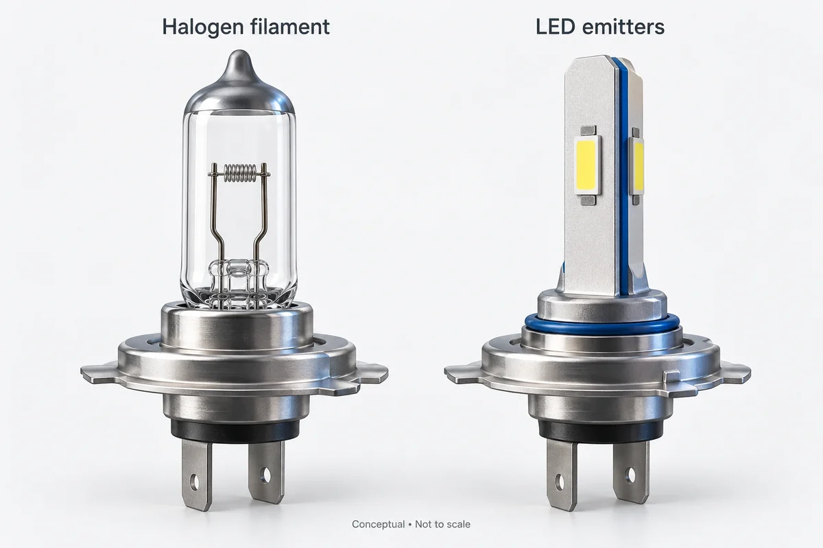
Practical takeaway: Assess luminous geometry and actual beam results together. Mechanical size similarity is useful information, not a performance guarantee.
02 · How LED Upgrades Affect Reflector Headlight Beam Patterns
Reflector facets direct light from the intended source toward different areas of the road. If an emitter moves forward, backward or sideways relative to that design, the reflected rays can land elsewhere. A larger luminous area can also broaden or blur parts of the distribution.
Incorrect orientation, PCB shadowing or incomplete seating can create stray light, hot spots, dark zones or weak reach. Reflector compatibility depends on the specific bulb and headlamp optical system.
03 · How LED Upgrades Affect Projector Headlight Beam Patterns
A typical low-beam projector combines a reflector bowl, light source, cutoff shield and lens, although details vary. The reflector gathers light and the lens projects the distribution formed around the shield. Each component participates in the result.
Keeping the original cutoff shield does not make an LED conversion optically correct. A mismatched source can alter hot-spot position, foreground intensity, width, cutoff sharpness and light above the intended cutoff. The shield may leave a recognizable edge while useful intensity below it deteriorates.
Practical takeaway: A visible cutoff alone does not prove good optical performance. Inspect the distribution as well as its upper boundary.
04 · Why LED Headlight Upgrades Can Create Glare
Glare is not simply a synonym for high lumen output. Light directed into an oncoming driver’s viewing area can cause discomfort or reduce visibility, even when useful road illumination is disappointing. Several causes need separate checks.
Emitter Position
An offset from the intended source location changes how the optics redirect light. A bulb that fits mechanically may still place its luminous area incorrectly.
Emitter Size
A broad emitting surface or widely spaced emitters can illuminate optical regions differently from the original filament, changing concentration and spill.
Incorrect Seating
A tilted base, unsuitable adapter or incomplete locking can shift the entire source. Confirm seating before evaluating orientation or adjusting the headlamp.
Bulb Orientation
Rotation changes which reflector areas see the emitters and substrate. Follow the instructions for the exact bulb and application rather than a generic clock position.
Optical Mismatch
Some source-and-housing combinations cannot deliver the intended distribution. Increasing power or repeatedly rotating the bulb does not establish compatibility.
Headlamp Aim
Aiming controls where the complete beam points. Excessively high aim can create glare even with suitable optics; lowering aim cannot correct a distorted distribution.
05 · Why Dark Spots and Uneven Beam Patterns Appear
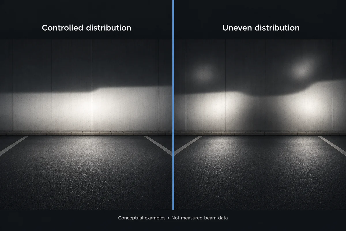
Dark regions can develop when the replacement source supplies too little light to optical areas responsible for part of the beam. Emitter spacing, source placement and substrate thickness may change how the reflector is illuminated or introduce shadowing in particular designs.
Incorrect seating or optical mismatch can weaken central intensity. Not every LED PCB creates a dead zone. Rule out reflector damage, cloudy lenses and installation errors when comparing sources.
06 · LED Bulb Clocking: Why Orientation Matters
Clocking means rotating the bulb’s emitting arrangement around its mounting axis. For some two-sided retrofit designs and particular headlamp optics, a left/right emitter orientation can give a distribution closer to the original source. The familiar 3 and 9 o’clock description is a reference for those applications, not a rule for every LED bulb.
Correct clocking depends on emitter layout, base and headlamp instructions. Check whether the prescribed orientation is viewed from the front or rear.
What an Adjustable Collar Can and Cannot Do
An adjustable collar can fine-tune permitted orientation; secure it as instructed. Rotation cannot correct wrong emitter geometry, base position or an incompatible optical system. Never force a keyed mount.
07 · Why a Sharp Cutoff Does Not Automatically Mean a Good Beam Pattern
The cutoff describes one boundary of a low beam; it does not describe every intensity within it. A sharp edge can coexist with a weak or displaced hot spot, narrow width, excessive foreground concentration or large dark regions.
Evaluate width, uniformity, distance illumination and spill together. Strong foreground light can mask weak reach. Some above-cutoff light is intentional in particular designs; photographs cannot establish compliance.
08 · How to Check the Beam Pattern After an LED Upgrade
Where the replacement is permitted, compare sources under consistent conditions. A wall check screens for obvious changes; it cannot certify performance.
- Use level ground facing a vertical wall; keep vehicle position, loading and test conditions consistent.
- Observe each headlamp separately using a suitable non-contact method; do not cover a hot lamp with flammable material.
- Confirm the correct bulb variant, fully seated base, required adapter and prescribed orientation.
- Compare cutoff shape, hot-spot location, width, uniformity and obvious stray light or dark zones.
- Check both low and high beam where applicable, then have aim verified using the vehicle procedure and suitable equipment.
Formal aiming must follow the vehicle manufacturer’s procedure or applicable local standard. Do not apply a universal distance, drop or percentage. Do not manually create a left/right height difference unless the relevant procedure specifies it. Traffic side and headlamp design can change the intended cutoff shape.
09 · Signs Your LED Headlight Beam Pattern May Be Incorrect
- Unexpected stray light above the intended cutoff or a major change from the original beam.
- A weak, split or displaced hot spot, or large dark zones.
- Strong foreground concentration with weak distance illumination.
- Unexpected uneven left/right distribution after accounting for the designed beam asymmetry.
- A bulb that is tilted, loose or not fully seated.
If distribution remains poor after correct installation, return to the specified source or a verified compatible solution. Changing aim cannot establish compatibility, and a brighter wall does not prove improvement.
10 · Why More Lumens Do Not Guarantee a Better LED Headlight Beam
Lumens describe total luminous flux, not its placement on the road. Headlamp optics, operating temperature and source geometry affect how much output becomes useful illumination. More total light can still produce weaker intensity in an important direction or more unwanted spill.
Request complete-system beam data under stated conditions, including stabilized output. Color and photographs alone cannot establish beam quality.
11 · Optical Compatibility, Road Use and Compliance
Changing the source in a headlamp originally designed or approved for another source type may affect beam performance, compliance and road legality. Requirements depend on the country, market, headlamp, vehicle and replacement product. Approval scope and any required accessories must be checked for the actual application.
Plug-and-play fitment and a good-looking cutoff are not proof of legal road use. Do not infer that all NVEL LED headlights are approved for every halogen or HID housing. An HID projector was designed around an arc source rather than a filament; a D Series LED replacement therefore needs its own application-specific optical and road-use checks.
12 · What to Look for in an LED Headlight Upgrade
Start with the correct base and vehicle application, then assess compact emitter geometry, position, secure seating and orientation provisions where appropriate. Closer reproduction of the original luminous-source geometry can improve optical compatibility, but a “1:1” label alone does not guarantee the original beam, glare control or compliance.
Check thermal clearance, heat dissipation and driver compatibility, including vehicle lamp monitoring or CANBus requirements where relevant. Electrical compatibility and optical compatibility are separate questions. Request fitment information for the actual headlamp type and verify the beam after installation.
For example, NVEL’s O1 Mini LED Headlight Bulb Kit lists H7, H4 and H15 configurations with an integrated driver. These are product options, not a universal vehicle approval. Review the LED Headlights range and confirm the exact application with the supplier. The Technical Guides hub provides further lighting guidance.
Frequently Asked Questions
Why does my LED headlight beam look scattered?
Source position, emitter size, orientation, seating or optical mismatch may be changing the distribution. Verify installation against the exact product instructions before adjusting aim.
Do LED bulbs work in reflector headlights?
Some combinations can provide controlled results, but socket fit alone is insufficient. Confirm the specific bulb, headlamp, application and applicable road-use requirements.
Do LED bulbs work in projector headlights?
A projector does not automatically make a retrofit suitable. Its reflector and lens still depend on source geometry; inspect intensity distribution as well as the cutoff.
Should LED chips face 3 and 9 o’clock?
That orientation suits some designs. Follow the exact bulb and headlamp instructions; keyed or application-specific installations may require another orientation.
Why do LED headlights create dark spots?
Emitter spacing, source placement, substrate shadowing or incorrect seating can leave parts of the beam under-illuminated. The cause depends on the complete optical combination.
Does a sharp cutoff mean the LED bulb is properly aligned?
No. A clear boundary can remain while the hot spot, width or useful intensity is wrong. Check seating, prescribed orientation, aim and the full distribution.
How do I check the beam after installing LED headlights?
Compare before and after on level ground against a vertical wall under consistent conditions, then verify aim using the vehicle procedure. A wall check does not establish approval.
Looking for an LED Headlight Upgrade with Controlled Beam Performance?
Discuss bulb fitment, emitter geometry, headlamp type and vehicle application with NVEL before choosing a replacement. Share the original source type and target market so the relevant product information and optical evaluation needs can be reviewed.
Request model-specific specifications, application-specific beam verification and relevant road-use documentation.