TECHNICAL GUIDES · PRODUCT DEVELOPMENT
How to Develop a Custom Automotive LED Lighting Product: From Requirement to Mass Production?
A practical six-stage roadmap for automotive brands, distributors and OEM/ODM buyers—from product requirements to controlled mass production.
October 9, 2026 · 10 min read
Introduction
Bringing a custom automotive LED lighting product to market—whether a Bi-LED projector module, an off-road pod light or a replacement headlight bulb—requires more than an attractive industrial design. Optics, thermal management, electronics, fitment and manufacturing must work together in the intended application.
For brands, distributors and importers, custom automotive LED lighting product development is a sequence of documented decisions. A clear engineering roadmap helps prevent expensive tooling revisions, uncontrolled substitutions and launch delays. This guide follows six stages from requirement definition to Start of Production (SOP), with approval gates buyers can use to manage an OEM or ODM project.
Custom Automotive LED Lighting Development
QUICK GUIDE
Define the application, target market, engineering requirements and acceptance criteria before design begins.
Review optics, cooling, electronics and installation together; correlate simulations with physical measurements.
Evaluate fitment and function with identified prototype revisions, then close critical design risks.
Approve tooling and verify production-intent samples against the documented test plan.
Validate the production process, control the approved configuration and retain traceability after launch.
1. Requirement Definition and Product Design
A successful project begins with a Product Requirements Document (PRD) that connects customer needs to measurable engineering targets. Define the lighting function, vehicle applications, target markets, expected order volumes and commercial positioning before choosing components or authorizing molds.
Critical Parameters in the PRD
- Optical performance: Specify stabilized output, beam distribution, measuring distance, aiming conditions, color temperature and applicable glare limits. Lumens and lux describe different properties; a peak lux value alone does not define a compliant beam.
- Electrical interface: Agree the supply range, current and power limits, connector, pinout, protection features and vehicle diagnostic behavior. A 9–32 V design is a possible project requirement, not a universal specification.
- Operating environment: Define ambient temperature, installation enclosure, humidity, vibration and ingress exposure. Separate operating limits from storage and accelerated test conditions.
- Market requirements: Identify the applicable road-lighting, EMC and environmental requirements for the exact device and installation. Allocate testing and approval responsibilities before design freeze.
- Mechanical and branding constraints: Record mounting points, clearance, housing dimensions, service access, appearance and packaging requirements.
The first approval gate is a signed requirements baseline with a verification method for each critical characteristic. Assign an owner and acceptance criterion to every open issue. Later changes should state their effect on cost, tooling, validation and delivery.
2. Optical, Thermal and Electrical Engineering
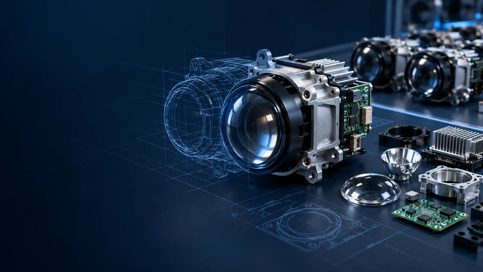
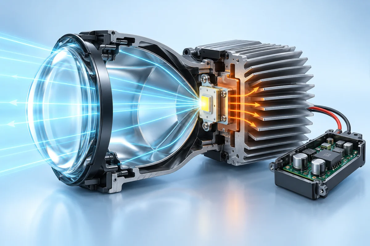
Computer-aided design and engineering help identify conflicts before production tooling is cut. Optical, thermal, electrical and mechanical work should proceed together: changing an LED position, drive current or heat sink can affect several performance targets at once.
Optical Engineering and Ray Tracing
Ray-tracing software can evaluate reflector surfaces, TIR lenses, projector shutters and lens geometry. Engineers review the required distribution, cutoff where applicable, hotspot, stray light and sensitivity to tolerances. The correct pattern depends on the lamp function and intended traffic direction; one cutoff shape does not suit every market or product.
Thermal and Electrical Feasibility
Thermal simulation estimates heat flow through the LED board, interfaces, housing and cooling system. Select a junction-temperature target from the actual LED and component ratings, lifetime objectives and installation conditions rather than assuming that 120°C is universally safe. Verify sustained output and derating after the assembly reaches thermal equilibrium.
Driver design should address supply variation, protection, switching behavior and electromagnetic compatibility. Mechanical reviews consider sealing, tolerance stack-up, cable routing and assembly access. Simulation guides decisions but must be correlated with physical measurements; it does not replace prototype or production validation.
3. Prototyping and Engineering Validation
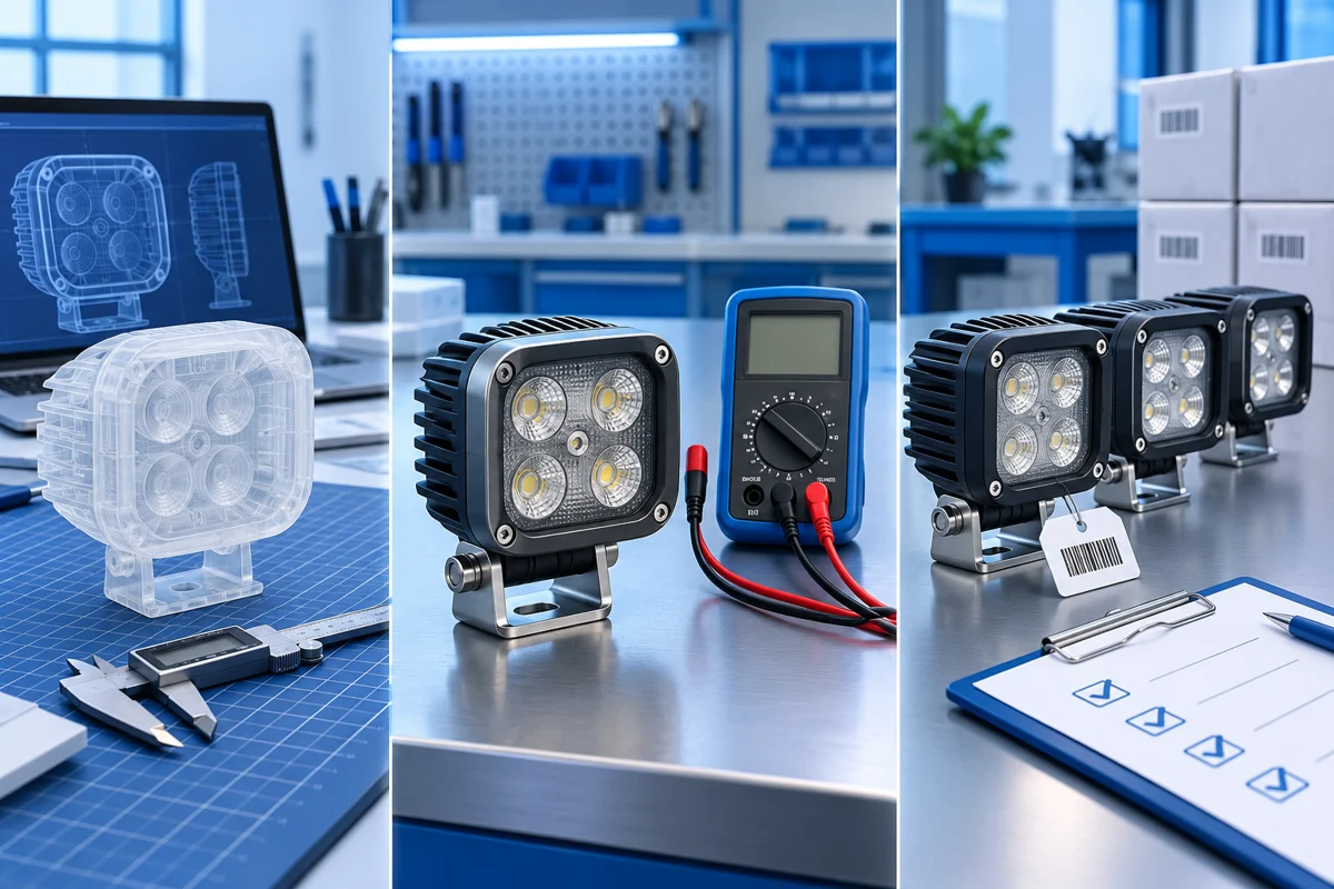
Prototype parts turn the design into evidence. SLA printing, CNC machining and prototype PCB assembly can check fitment and basic function before expensive tools are committed. Record the material, process and revision of each sample because a printed housing or machined optic may behave differently from a molded production part.
Development and Prototyping Stages
| Development Phase | Primary Methods and Tools | Key Validation Goals |
|---|---|---|
| Concept prototype | SLA printing, CNC parts and prototype PCB assembly | Fitment, installation, basic electrical function and preliminary beam |
| Engineering sample | Tool-trial parts and representative electronics | Dimensions, photometry, stabilized thermal performance and design risks |
| Validation sample | Production-intent materials, tooling and assembly | Defined environmental, ingress, vibration, EMC and durability requirements |
Use a sample evaluation report to connect each result to the PRD. Photograph installation issues, record test conditions and list unresolved failures. Do not approve tooling solely from an attractive beam photograph or a brief bench demonstration. Close the critical design risks first.
4. Tooling Development and Design Verification
Tooling is a significant one-time investment. A design-for-manufacture review should confirm materials, tolerances, mold layout, optic surface requirements and inspection access before release. Agree trial schedules, correction responsibilities and acceptance criteria for die-casting, injection molding and other required tools.
- Tool release: Approve controlled drawings, material specifications and the tooling quotation. Identify every tool and the intended production revision.
- Tool trial: Inspect initial trial parts for dimensions, surface finish, sealing interfaces and optical alignment. Tool-trial labels such as T0 or T1 vary by supplier; define their meaning in the project plan.
- Design Verification (DV): Test production-intent samples against the approved design requirements. Keep reports tied to the exact configuration and sample identities.
A Project-Specific Verification Plan
Photometric equipment may include an integrating sphere for luminous flux and a goniophotometer for angular intensity distribution. Environmental testing can cover thermal cycling, thermal shock, vibration and humidity. Select temperatures, cycle counts, durations and acceptance limits for the intended application instead of copying a universal 100-cycle or 1,000-hour requirement.
Ingress tests must match the requested rating. IP68 addresses dust protection and immersion under specified conditions; high-pressure water-jet resistance is a separate requirement. EMC requirements and limits also need to be defined for the application. Maintain a failure log, implement corrective actions and repeat the relevant tests after material or design changes.
5. Pilot Production and Process Validation
A pilot run tests whether the production process can repeatedly build the approved design. Production or process validation (PV terminology varies between organizations) should use representative operators, equipment, fixtures, materials and inspection steps. A hand-built engineering sample cannot demonstrate normal line consistency.
- PCB and electronics: Validate the applicable assembly process, reflow profile, solder quality and inspection coverage. AOI, electrical tests or other methods should be selected for the actual assembly.
- Assembly controls: Check fixture alignment, lens positioning, sealing, adhesive application, torque and error prevention. Identify the characteristics that need ongoing measurement.
- Functional and aging tests: Establish appropriate checks for power, switching and output. Burn-in conditions and duration must be validated for the product; elevated voltage or heat should not be imposed without an engineering basis.
- Traceability: Connect component lots, assembly dates, test results and product revisions so a defect can be investigated and contained.
Review pilot yield, rework, scrap, cycle time and inspection results. Correct recurring problems before ramp-up. The approval gate should confirm both design performance and process readiness, including how nonconforming units are segregated and released.
6. Start of Production and Continuous Control
SOP begins after the agreed design and process gates are closed and the buyer has approved the production configuration. Start with a controlled ramp rather than assuming that the first full batch will behave like laboratory samples. Confirm material availability, line capacity, packaging and shipment inspection arrangements.
Freeze the approved bill of materials, drawings, firmware where relevant and work instructions. Require written change notification for substitutions or process changes that may affect fitment, reliability or compliance. Keep golden samples under controlled storage with their revision and acceptance records.
Production quality continues after launch. Monitor defects, field feedback and component changes; use the traceability record to investigate returns. Repeat validation when the agreed change criteria require it. A successful development process produces a repeatable product and a maintainable evidence package.
Pre-SOP Checklist for Custom Buyers
- Engineering sign-off: Approve final drawings, PCB design, firmware where applicable and the controlled BOM.
- Golden samples: Retain mutually approved samples with identified revisions and documented acceptance criteria.
- Test package: Obtain the agreed photometric, electrical, thermal, environmental and EMC results for the final configuration. Record unresolved limitations and applicable approval documents.
- Production readiness: Review pilot results, inspection methods, traceability and change control.
- Packaging approval: Confirm artwork, labels, barcodes, instructions, carton specifications and transport validation.
- Commercial terms: Agree pricing, MOQ, lead-time milestones, warranty handling and defect investigation. Define sampling and AQL criteria by defect class; AQL is not a promise that a fixed percentage of defects will occur.
- Rights and responsibilities: Document tooling, IP, access to engineering files and responsibility for market compliance.
Development Budget, Timeline and Tooling Rights
Request an itemized Non-Recurring Engineering (NRE) proposal separating design, prototypes, tools, fixtures, tests and approvals. Scope, complexity and available platform assets determine cost and timing. The original concept may require several development iterations; an ODM modification can also need fresh validation. Use a milestone schedule rather than treating a quoted month range as a guarantee.
Paying for tooling or engineering does not automatically transfer every CAD file or background technology. Define asset ownership, storage, permitted use, maintenance, transfer rights and deliverables in the project agreement. An NDA protects the agreed confidential information; exclusivity and IP rights need their own explicit terms.
Planning a Custom Lighting Project with NVEL
Start a discussion with NVEL by sharing the lighting function, vehicle application, target market, performance targets, expected volumes and customization needs. Ask the team to identify a suitable existing platform or propose a development scope, with samples, testing and commercial milestones confirmed for your project.
Review NVEL’s automotive lighting solutions and product catalog to prepare your brief. Confirm the engineering resources, production processes and documentation available for the selected product rather than assuming that every project follows identical equipment or test conditions.
Frequently Asked Questions
How long does custom automotive LED light development take?
Timing depends on the development scope, tooling, component availability, test plan and approval iterations. Ask for milestones from requirements approval to SOP. Adapting an existing platform can reduce work, but substantial changes still require engineering and validation.
What is the typical NRE cost?
There is no universal cost range. Request separate prices for design, prototypes, tooling, fixtures and testing, with deliverables and payment gates. A simple adaptation and a new optical system should not be budgeted as equivalent projects.
Who owns custom tooling and intellectual property?
The project agreement determines ownership, access and use rights. Separate supplier background IP from project deliverables, and list each tool and file explicitly. Funding NRE does not by itself establish complete ownership.
Why use optical ray tracing before prototypes?
It helps predict distribution, cutoff where required and sensitivity to geometry changes before physical parts are made. It can reduce avoidable iterations, but physical photometric testing remains necessary to verify the finished assembly.
What is the difference between DV and PV?
DV checks that the design meets its requirements. PV checks production readiness and repeatability using production-intent processes. Organizations may use different terms, so define the sample source, tests and approval gate in writing.
Can one design serve North American and European markets?
Potentially, but market requirements and approval routes differ. Evaluate the exact lamp, optical configuration and installation for each intended market. Neither a design claim nor a test for one market establishes compliance in every other market.
What is a golden master sample?
It is a mutually approved reference unit representing the agreed product revision. Use it alongside controlled drawings, specifications and test records; a sample alone cannot capture every electrical, environmental or reliability requirement.
Conclusion
Custom automotive LED lighting product development succeeds when requirements, simulation, prototypes, tooling, verification and production control form one documented process. Buyers should approve evidence at each gate, allocate responsibilities and manage changes before scaling orders.
Use the six-stage roadmap and pre-SOP checklist to build a clearer project brief and a more reliable launch plan. Explore the Technical Guides Hub for related sourcing and engineering topics.
Develop Your Custom Automotive LED Lighting Product
Share your product brief with NVEL to discuss OEM/ODM options, sample development, validation requirements and a project-specific production plan.