TECHNICAL GUIDES · ELECTRICAL COMPATIBILITY
CANBus LED Headlight Compatibility: What Distributors Should Know
NVEL · Distributor Sourcing Guide · 12 min read
October 19, 2026
For distributors, importers and automotive lighting brands, an LED bulb that fits the socket can still create dashboard warnings, flicker or intermittent shutdown. These problems increase support costs and make application claims difficult to defend. Effective canbus led headlight compatibility sourcing therefore starts with the vehicle circuit, the exact LED product and a documented validation process.
This guide separates vehicle communication from lamp monitoring, compares external compatibility accessories with integrated drivers, and provides a practical troubleshooting matrix. Its purpose is to help buyers select and validate suitable combinations, rather than promise fault-free installation across every vehicle. Electrical operation, physical fit, optical performance and road-use legality must each be assessed.
Quick Guide
How Vehicle Lighting Diagnostics Work
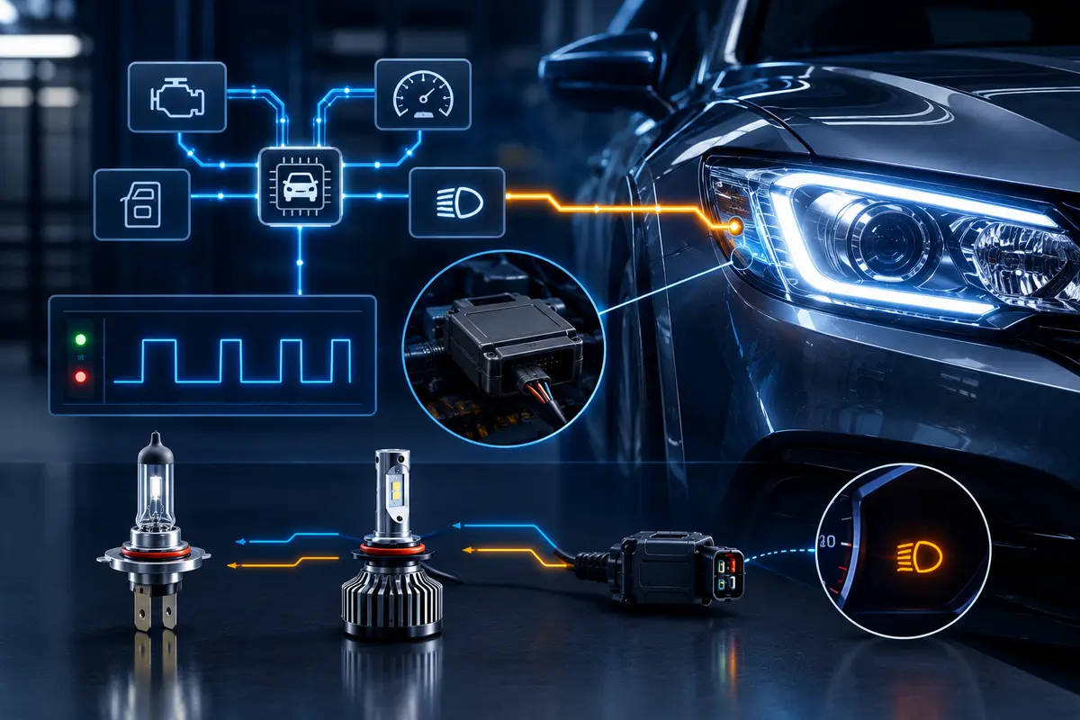
CAN stands for Controller Area Network, a network used for data communication between vehicle electronic control units. A body control module (BCM), instrument cluster or dedicated lighting controller may exchange commands and fault information over CAN. The communication network and the electrical output supplying a conventional headlight bulb perform different functions.
In the aftermarket, “CANBus LED bulbs” usually describes products designed for compatibility with vehicle lighting diagnostics. It does not mean the replacement bulb necessarily communicates directly through CAN. A conventional bulb typically receives electrical power through its connector; a control unit monitors that circuit and may report a fault over the vehicle network. Complete network-controlled headlamp assemblies are a separate product category.
Current sensing and load behavior
A controller may monitor current, voltage or other circuit responses to detect an open circuit, short circuit or unexpected load. An LED replacement often consumes less electrical power than the original halogen lamp, but actual consumption depends on the bulb specification, operating voltage, beam function and driver design. There is no single current range or wattage that establishes compatibility with every BCM.
Steady-state power is only part of the picture. Startup current, input capacitance, diagnostic-pulse response and protection behavior can affect the controller’s interpretation. Request measured input characteristics for the selected SKU, including stabilized operation after warming up. Compare these with application-specific requirements instead of treating higher wattage as a universal cure.
Cold diagnostics
Some vehicles check a lamp circuit while the lamp is commanded off, using brief diagnostic pulses or another monitoring strategy. A halogen filament may show no noticeable light during such a check, while an LED driver may respond with a short flash. Pulse timing, duration and repetition depend on the vehicle and its software; not every vehicle sends identical pulses at every startup.
Distinguish these checks from monitoring while the lamp is operating. Record whether a symptom occurs with ignition on, lights off, engine running or during a particular lighting mode. This information helps the supplier investigate the actual input conditions and avoids labeling every electrical fault as a CAN protocol problem.
Bulb-Out Warnings and PWM Flicker
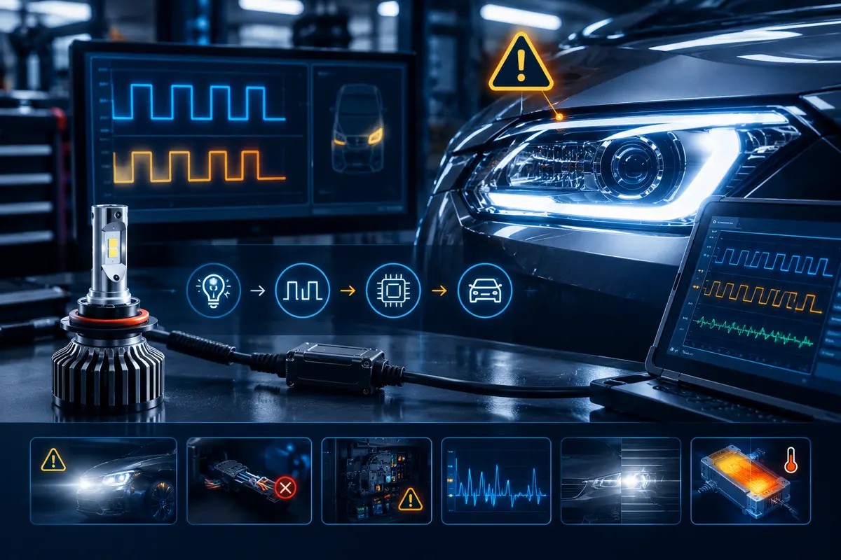
A bulb-out warning can occur when a functioning LED produces an electrical response outside the vehicle’s expected limits. It can also reflect a genuine problem such as an open connection, damaged harness or failed driver. Check fault information and restore a known-good original bulb where appropriate before deciding that additional load is required.
Pulse width modulation (PWM) controls a lighting function by switching the supply or control signal on and off with a defined duty cycle. A filament’s thermal inertia can smooth the visible output. An LED driver must manage the particular waveform correctly; incompatible behavior may produce brightness variation, repeated restarting or unstable operation. Input PWM handling and internal LED dimming are related concepts, but they are not automatically interchangeable capabilities.
PWM is one possible cause of flicker, not a diagnosis by itself. Voltage instability, poor grounds, loose connectors, driver incompatibility, thermal protection and BCM output behavior can produce similar symptoms. A stable bench supply demonstration does not reproduce every vehicle’s diagnostic pulses or pulsed power output.
For sample evaluation, document startup, low and high beam, daytime running functions where applicable, engine stop-start transitions and sustained operation. Measure the supply at the relevant connection using appropriate equipment and service procedures. Keep instrumented waveform observations separate from customer descriptions; camera banding alone is not proof of a particular electrical fault.
Do not defeat safety diagnostics, raise fuse ratings or repeatedly add accessories to suppress a warning without understanding its cause. A suitable compatibility solution should preserve reliable lamp operation and allow genuine failures to remain detectable according to the vehicle’s intended behavior. Professional circuit diagnosis is appropriate when wiring or controller faults are suspected.
External Decoders vs. Integrated LED Drivers
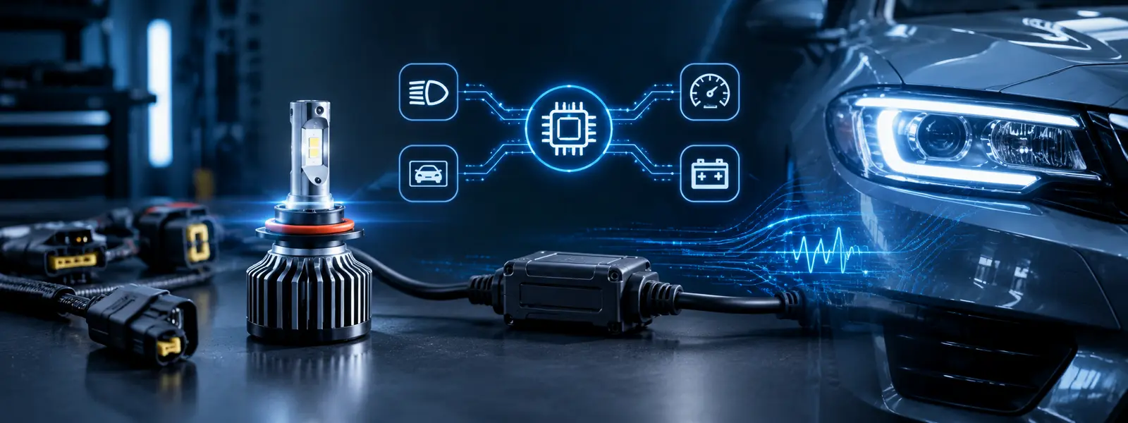
“Decoder” is a broad market term. An external module may add load, filter particular input signals, stabilize power or combine functions. A simple load resistor changes the electrical load seen by the monitoring circuit. It does not inherently decode CAN messages, smooth PWM or provide radio-frequency filtering. Specify the required function before selecting an accessory.
Resistors consume additional electrical energy and release it as heat. Surface temperature depends on resistance, applied voltage, power dissipation, mounting, ventilation and duty cycle; no fixed temperature applies to all products. Verify electrical ratings, safe mounting instructions, thermal clearance and harness compatibility. Keep heat-producing parts away from plastics, seals and cable insulation, and follow product-specific installation instructions.
Integrated LED drivers may provide input protection, voltage regulation, PWM handling, filtering or load-management circuitry. Features vary by product and circuit revision. An intelligent IC label does not establish that every function is included. Integrated designs also generate heat and have installation limits, so request documented capabilities and application evidence rather than assuming 100% plug-and-play operation.
| Comparison Factor | External Load Resistor / Decoder | Integrated LED Driver |
|---|---|---|
| Main Function | Adds load and/or manages specified input behavior; depends on module design. | Regulates LED operation; additional compatibility functions vary. |
| Electrical Load | May substantially increase total circuit current. | Input demand depends on driver design and operating mode. |
| Heat Generation | Resistive load dissipates added power as heat; mounting matters. | Driver losses and load-management circuits also create heat. |
| PWM Handling | A resistor alone does not inherently filter PWM. | Supported waveform ranges must be documented and tested. |
| Installation | Additional connectors, space and secure mounting may be needed. | Bulb, driver and dust-cap clearance still require checks. |
| EMC Considerations | Compatibility labeling does not establish emissions performance. | Switching design, filtering and wiring affect emissions. |
| Vehicle Compatibility | Validate the exact vehicle, bulb and accessory combination. | Validate the exact vehicle, SKU and driver revision. |
| Limitations | Cannot repair wiring faults or guarantee universal compatibility. | Cannot guarantee every monitoring strategy or legal retrofit. |
Diagnostic compatibility and EMC are different
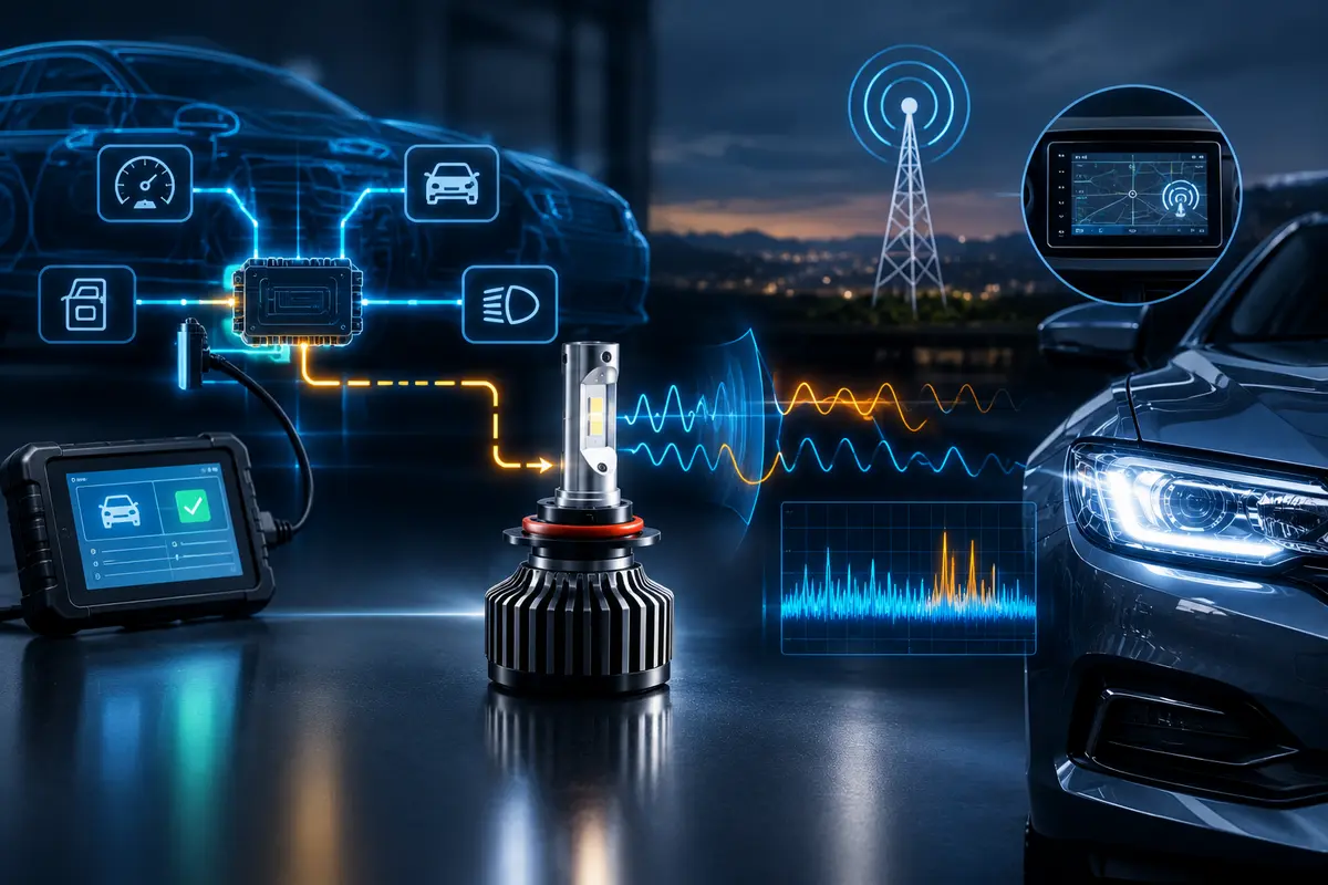
Lamp-diagnostic compatibility concerns how the vehicle interprets the lighting circuit. Electromagnetic compatibility concerns electrical disturbances and their effects on other equipment. A bulb can operate without warnings yet interfere with a receiver, or exhibit a warning without causing radio noise. These require separate evidence and checks.
CISPR 25 addresses radio disturbances relevant to protection of on-board receivers. A report should identify the tested product, standard edition, test methods, limits and configuration. Passing a stated class under defined conditions does not guarantee the absence of FM, GPS or other interference in every installation. Driver switching noise, grounding, cable routing and filtering remain relevant at vehicle level.
LED Headlight Compatibility Troubleshooting Matrix
Use the following matrix to organize investigation. Possible causes can overlap, and the symptom alone does not establish a single root cause. Qualified technicians should follow vehicle service information, use suitable measurement methods and avoid exposing themselves to hot components or damaging control electronics.
| Symptom | Possible Causes | Recommended Checks |
|---|---|---|
| Bulb-Out Warning | Current sensing, load mismatch, abnormal diagnostic response or circuit fault. | Record fault codes and lighting mode; compare original bulb operation, connections and documented input behavior. |
| Flickering | PWM interaction, unsuitable driver, voltage instability, connector fault or controller behavior. | Record when it occurs; check voltage, grounds, connectors and relevant waveforms before selecting a verified filter or driver. |
| Radio Interference | Driver switching noise, cable routing, grounding or inadequate filtering. | Compare receiver behavior with lamps on/off; review product-specific EMC evidence and installation routing. |
| One-Sided Failure | Connector damage, polarity where relevant, driver fault or vehicle control output. | Inspect the affected circuit; verify polarity and supply using service procedures; compare known-good components where appropriate. |
| Shutdown After Operation | Thermal protection, supply interruption, excess load or vehicle control logic. | Check cooling clearance and temperatures, sustained input behavior and controller fault records; investigate before adding load. |
Begin with the least invasive checks: confirm the correct bulb base and function, inspect the installation, record operating conditions, then compare a known-good original lamp. If accessories are evaluated, change one variable at a time and retain the original baseline. Recheck both sides, every relevant operating mode and sustained operation after any proposed correction.
A successful warning reset is not proof of a durable fix. Repeat the conditions that previously produced the symptom, inspect connectors and mounting, and confirm that the complete combination remains within documented ratings. Escalate unresolved faults to the supplier with the exact SKU, vehicle configuration and observations rather than prescribing one generic decoder to every customer.
Distributor Sourcing and Validation Checklist
Create a compatibility matrix before approving a new range. Each row should identify vehicle make, model, model year, headlamp type, original bulb specification and LED product SKU. Include warning status, flicker status, installation notes and test date, plus vehicle firmware/software context where available. Record the accessory SKU and driver revision if used; do not merge different combinations into one result.
Define what “pass” means for your market and application. Include correct lighting functions, acceptable diagnostic behavior, sustained operation and safe installation. Add optical assessment and legal eligibility as separate gates. A test on one trim or headlamp option cannot automatically qualify all vehicles bearing the same model name.
- Target Vehicle Applications: Agree on specific models, years, headlamp configurations and exclusions; avoid brand-wide compatibility promises.
- Electrical Specifications: Request rated input conditions, actual stabilized consumption, startup behavior and protection functions for the exact SKU.
- PWM Behavior: Obtain supported input waveform information and sample results under representative vehicle conditions.
- Bulb-Out Warning Testing: Check relevant off-state diagnostics and operating modes; retain warning records and known limitations.
- Thermal Safety: Evaluate bulb cooling, driver placement and accessory mounting in the actual installation, including dust-cap clearance.
- EMC Documentation: Match reports to the product revision and test configuration; investigate receiver interference independently.
- Installation Compatibility: Check sockets, locking adapters, polarity where applicable, harness routing, seals and service access.
- Warranty and Support: Agree on application exclusions, diagnostic information required, accessory policy and how product revisions trigger revalidation.
Use representative samples and document failures as carefully as passes. Keep a controlled approved sample and link incoming batches to the validated revision. Supplier changes to components, firmware, harnesses or accessories can affect results, so establish a review process before substituting parts. Return data should feed back into the matrix and published fitment information.
Road-use compliance
No dashboard warning and no visible flicker do not establish road-use legality. CANBus compatibility is separate from DOT-related requirements or E-Mark approval. Before sale for public-road use, verify the applicable requirements and approval scope for the exact light source, headlamp, vehicle application and destination market. Electrical validation must not be presented as regulatory approval.
Frequently Asked Questions
What Is CAN Bus?
CAN is Controller Area Network, used by vehicle electronic control units to exchange data. In conventional LED bulb listings, the CANBus label usually refers to compatibility with lamp monitoring rather than direct network communication by the bulb.
Why Do Some Vehicles Trigger LED Errors?
The controller may detect an unexpected load or diagnostic response, but genuine circuit faults can also produce warnings. Monitoring strategies differ by model, year, lighting equipment and software. Country of origin or vehicle brand alone cannot establish the cause.
Are External Load Resistors Safe?
They may be appropriate when correctly specified and installed for a validated application. They add electrical demand and heat. Verify ratings, mounting, thermal clearance and harness suitability, and use professional installation where appropriate. Do not use them to conceal a genuine fault.
CANBus Decoder vs. EMC Filter
A decoder is a broad label for a module addressing specified load or power-input compatibility. An EMC filter targets electromagnetic noise. A product may combine functions, but neither label proves that it resolves warnings, flicker and interference together.
Can Any LED Bulb Be Universally Compatible?
No universal claim can replace application testing. Vehicle circuits, software and headlamp configurations vary. Require a clearly scoped compatibility list, exact product revisions and documented limitations instead of unsupported global pass-rate percentages.
How Does NVEL Address Compatibility?
NVEL is a B2B automotive lighting manufacturer with 25+ years of experience and an OEM/ODM positioning. Discuss target applications and request specifications and validation evidence for the selected product. Compatibility depends on the exact product and vehicle combination, so agree on a clearly scoped validation plan before ordering.
Should Distributors Stock External Decoders?
Consider accessories when your validated applications show a recurring need and the module’s function is documented. Stock the verified bulb/accessory combinations with clear installation instructions and exclusions. An accessory should support diagnosis and suitable fitment, rather than be prescribed automatically for every warning.
Build a Verified Compatibility Range
Reliable sourcing combines application-specific electrical evidence, safe installation and controlled product revisions. Use the matrix to define where a product works, investigate failures systematically and keep compatibility claims within tested scope. Share your target vehicles, original bulb specifications and observed symptoms with NVEL when discussing product selection or OEM/ODM requirements.
Review the NVEL LED headlight product range when defining sample requirements.