TECHNICAL GUIDES · FOG LAMP OPTICS
SAE J583 FOG LIGHT & ECE R19 Fog Lamp Compliance: Optical Cutoff and Wide-Beam Dispersion
Understand standards, cutoff control, beam dispersion and model-specific compliance evidence.
Technical engineering guide · 15 min read
Introduction
For automotive lighting importers, fleet buyers and aftermarket distributors, a fog lamp’s beam pattern is more than a styling feature. A well-designed front fog lamp must illuminate useful roadway areas while controlling stray light that can distract its own driver or other road users. Product approval and installation legality also depend on the country, the applicable regulation, the vehicle, and the exact lamp assembly.
SAE J583 is a widely used technical reference for North American front-fog-lamp performance and evaluation. In UNECE markets, UN Regulation No. 19 remains significant for historical front-fog-lamp approvals, while UN Regulation No. 149 provides a consolidated road-illumination-device approval framework. A purchase decision must identify which edition, device class and national or regional legal pathway applies to the exact lamp.
These frameworks are related but not interchangeable. In the United States, fog lamps are optional lighting equipment under FMVSS No. 108 rather than a universally required lamp type; federal requirements for additional lighting and state-level rules must still be considered. In UNECE-type-approval markets, a valid approval relates to a specific lamp design and approved configuration—not to an arbitrary LED bulb, lens, or supplier claim.
This guide explores glare control, optical cutoff formation, horizontal beam dispersion, laboratory photometry, and a practical documentation checklist for B2B sourcing. Its purpose is to help buyers ask better engineering and compliance questions, not to imply that every NVEL product has already received a particular approval.
Table of Contents
Fog Lamp Compliance and Optical Engineering
QUICK GUIDE
01
SAE J583 vs. ECE R19 Standards
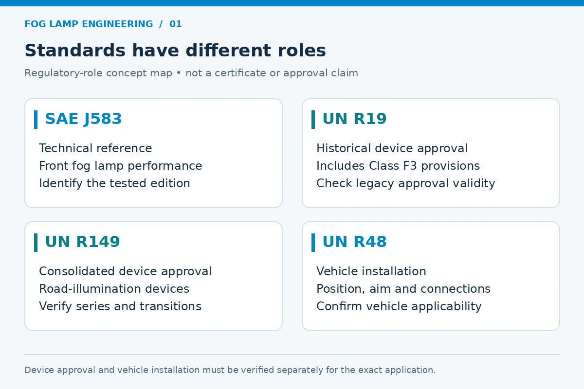
01 — SAE J583, UN R19 and UN R149: understand how engineering standards, device type approval, and vehicle installation rules differ.
02 — Cutoff-Line Optics: learn how reflectors, shields, projectors and TIR lenses manage light near and above the horizontal reference.
03 — Wide-Beam Dispersion: see why lateral coverage must be balanced against glare, uniformity and useful foreground illumination.
04
Photometric Goniometer Testing
04 — Photometric Goniometer Testing: examine how a measured beam is compared against the correct standard version and approval file.
05 — B2B Sourcing Checklist: verify reports, markings, assembly identity and target-market suitability before ordering.
1. SAE J583, UNECE R19 and UN R149: What Buyers Must Distinguish
1.1 SAE J583 fog light: an engineering standard, not a federal approval certificate
SAE J583 defines technical expectations and methods for front fog lamps. For B2B buyers, it provides a recognized reference when requesting optical design information, photometric verification, durability evidence, and installation guidance. A supplier should identify the exact revision used for testing; “SAE compliant” on a quotation is not a substitute for a traceable report.
In the United States, NHTSA has explained that front fog lamps are not required lamps under FMVSS No. 108. Additional lamps must not impair federally required lighting, and applicable state requirements can govern their use or installation. The term “DOT approved” should not be treated as a government-issued certificate for each front fog lamp.
1.2 UN Regulation No. 19 and the more recent UN R149 framework
UN Regulation No. 19 established a front-fog-lamp device approval framework, including Class F3 arrangements and associated marking conventions. UN Regulation No. 149 consolidated requirements for several road-illumination devices, including front fog lamps. Existing R19 approvals and newer R149 approvals may have different regulatory treatment depending on the vehicle category, amendment series and market.
UN Regulation No. 48 addresses vehicle installation requirements, including positioning, electrical connections and aiming provisions for the relevant vehicle classes. This is why a lamp’s device approval does not automatically establish legal installation on every vehicle.
1.3 Comparing the major regulatory concepts
| Topic | SAE J583 / U.S. market | UN R19 / UN R149 / UNECE markets |
|---|---|---|
| Primary role | SAE engineering standard for front fog lamp performance, tests, design and installation guidance. | UN device-approval framework for applicable front fog lamp classes; UN R48 addresses installation. |
| Legal mechanism | No generic NHTSA-issued “SAE/DOT fog-lamp certificate”; check additional-lighting, vehicle and state rules. | Type approval by an authorized approval authority for a specific design and regulated configuration. |
| Beam evaluation | Check applicable revision, test-point photometry, glare control, and installation guidance. | Check applicable regulation/amendment series, Class F3 or other allowed category, photometry, cutoff and approval conditions. |
| Markings and evidence | Treat SAE/DOT/SAE F style markings as claims requiring supporting product documentation. | Verify complete and valid approval markings, approval number, certificate and lamp identity. |
| Procurement decision | Do not equate a catalog claim with proof of legality in every U.S. state. | Do not assume a historical R19 approval automatically covers every new market or configuration. |
Important: this table compares regulatory roles, not exact photometric limits. Numeric pass/fail criteria must be taken from the authorized revision, lamp class and test procedure; they cannot safely be condensed into universal “800 cd” or “50-degree” rules.
2. Optical Cutoff Lines and Glare Control
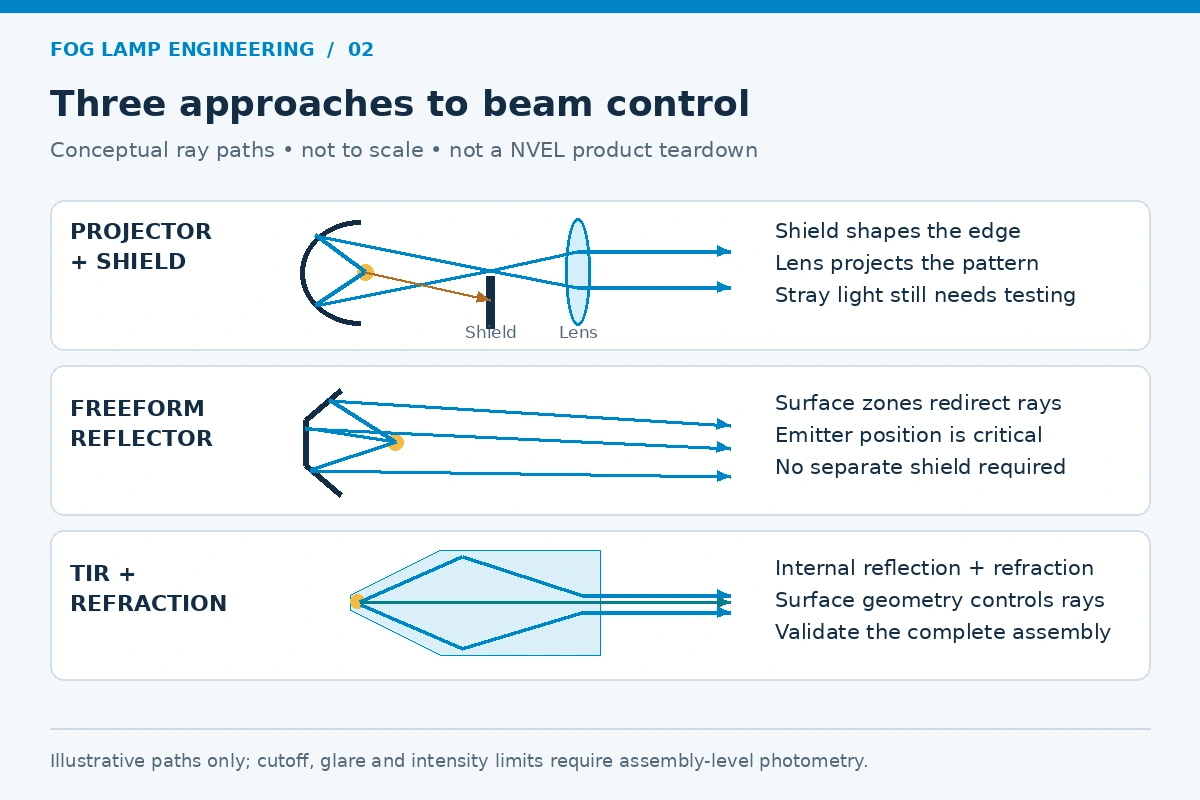
2.1 Why light above the intended distribution matters
Front fog lamps are typically mounted low and designed to distribute useful light near the road. Excessive upward intensity can create unwanted visual discomfort and may contribute to backscatter in fog, rain or snow. However, a fog-lamp specification should not be described as an absolute “zero-light zone”: all real optical systems have measurable distributions and must satisfy the relevant defined test points and zones.
The visual character of a cutoff alone does not prove compliance. A lamp can look sharp on a wall but still fail a test because of intensity distribution, aim, color, stability, or another requirement. Conversely, specific regulatory designs may permit different cutoff characteristics; the applicable standard and lamp class determine the measurements required.
2.2 Projector, reflector and TIR approaches
- Projector/shield systems: carefully positioned sources, reflectors, shields and projection lenses can shape the upper edge of the beam. The shield does not magically eliminate all stray rays; manufacturing tolerance, lens scatter and thermal alignment matter.
- Freeform reflector optics: a reflector can distribute light laterally and manage vertical intensity without a separate projector shield. The LED emitter position and surface finish must be controlled.
- TIR and refractive micro-optics: molded optical surfaces combine refraction and total internal reflection to control selected light paths. A TIR design is not inherently compliant without assembly-level testing.
For each optical architecture, teams should control emitter location, beam aiming sensitivity, thermal movement, optical material ageing and part-to-part consistency. A lamp intended for retrofitting into a halogen housing also requires housing-specific testing; a matching socket does not validate the beam.
3. Wide-Beam Dispersion, Road Edges and Uniformity
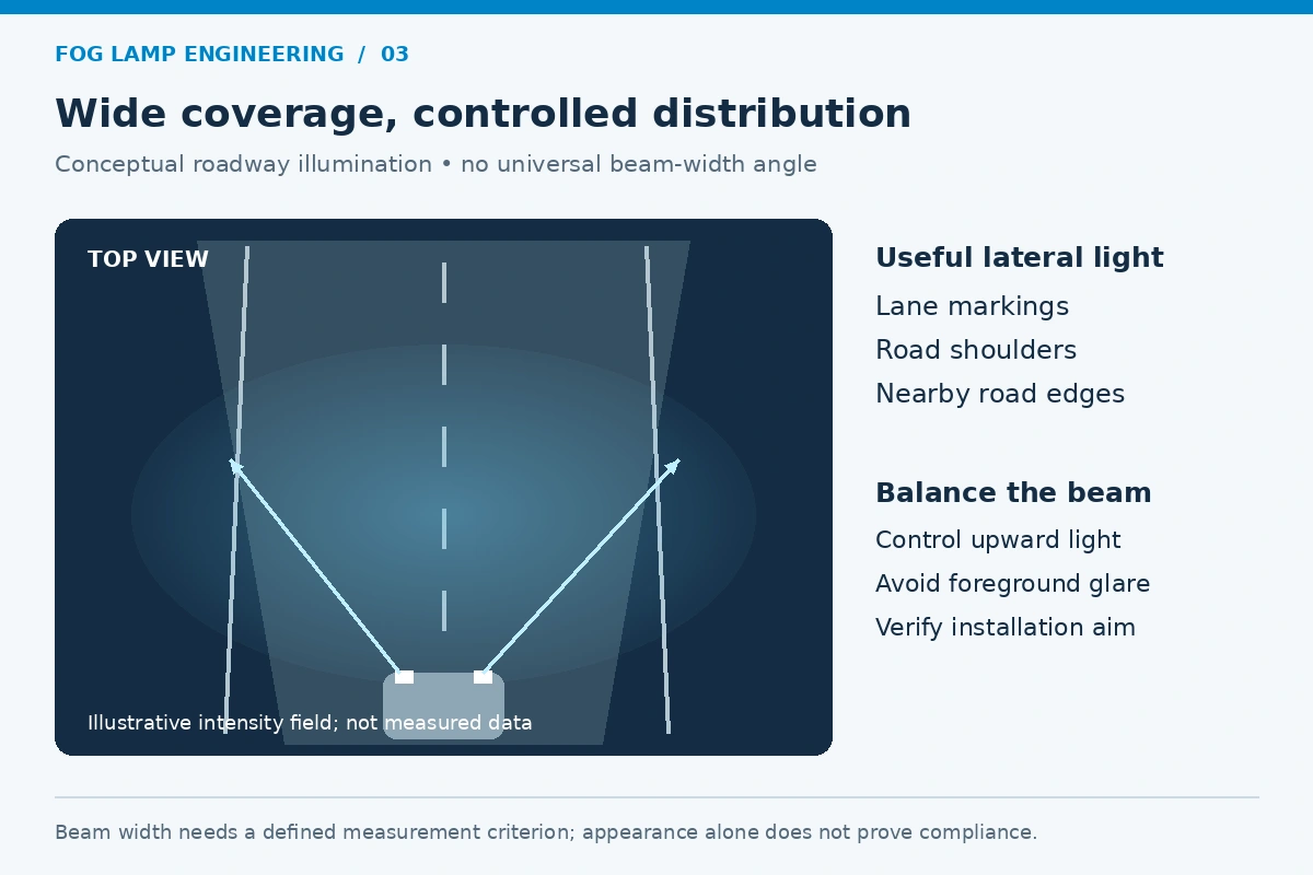
3.1 Horizontal coverage is a measured distribution, not one marketing angle
Fog-lamp optics aim to provide practical forward and lateral road illumination without exposing other road users to excessive glare. Wide horizontal distribution can help illuminate lane markings, curbs, shoulders and nearby roadside features. But more spread is not automatically better: over-bright foreground regions may reduce distance adaptation, while insufficient lateral coverage can leave useful road edges dark.
Beam width must be defined by a particular intensity or illuminance criterion before a numeric angle can be compared. Statements such as “all compliant lamps require 45–60 degrees” are therefore not adequate without the governing test definition.
3.2 Uniformity, photometric intensity and effective visibility
Candela describes luminous intensity in a direction; lux describes illuminance at a surface. Test engineers use angular intensity data and application-specific illuminance maps to evaluate the beam. Raw LED lumens or a brightly lit demonstration wall cannot show whether all required angular regions fall inside the regulatory minimum and maximum limits.
Beam assessment should consider horizontal symmetry where required, vertical intensity distribution, foreground hot spots, objectionable upward light, chromaticity, installation height and aim tolerance. The optimum pattern depends on both the lamp and the vehicle installation geometry.
3.3 Aiming cannot be treated as a universal one-degree rule
The correct setting depends on the vehicle, lamp design and applicable installation instructions or regulations. UN R48 contains provisions for front fog lamp installation and inclination under specified circumstances. For U.S. applications, follow the manufacturer’s validated aiming instructions and applicable state or vehicle requirements rather than copying a universal “1–4 degrees below horizon” claim.
4. Photometric Goniometer Testing and Compliance Evidence
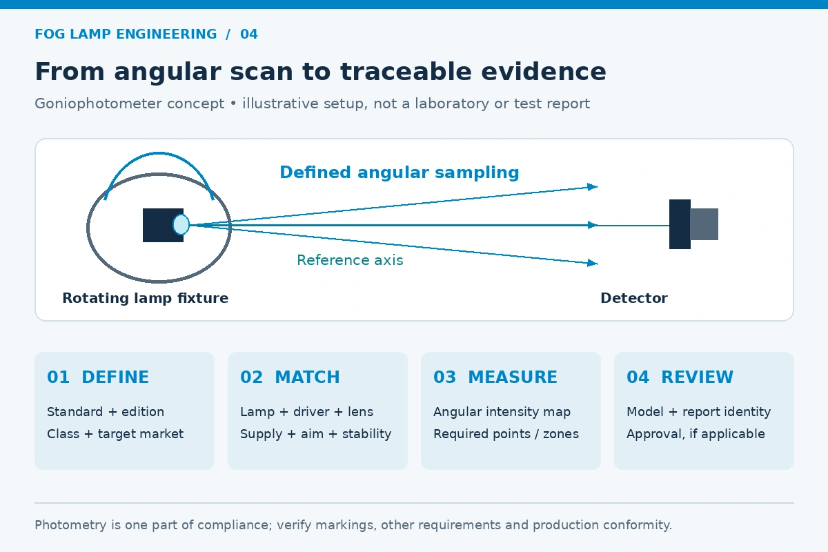
4.1 A laboratory test measures the complete assembly
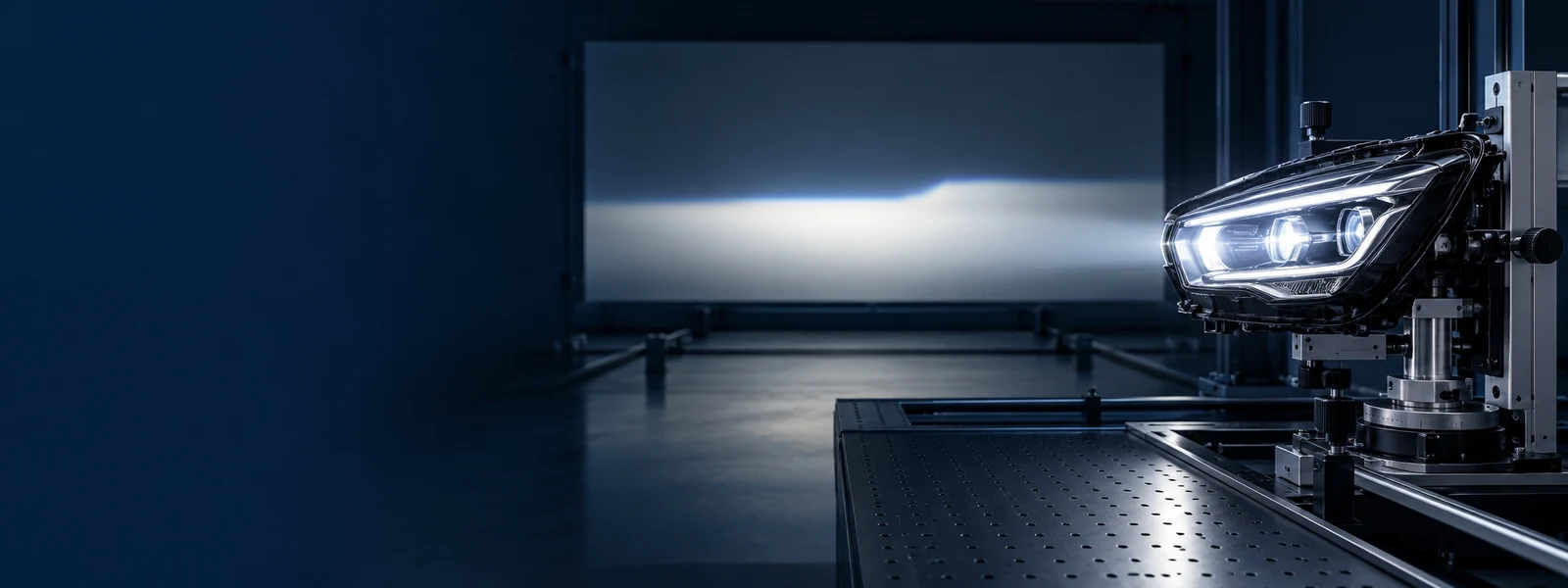
A goniophotometer measures light intensity at defined angles relative to a reference axis. Measurements may be converted or presented in screen-based representations as appropriate to the standard, but the test distance, angular grid, electrical supply, orientation and stabilization procedure must all follow the selected edition and method. A 25 m screen is not a universal rule for every measurement setup or market.
The lamp evaluated should be the actual marketed configuration: correct optics, LED modules, drivers, heat sinks, connectors, lenses and mounting conditions. If a brand modifies the source module or optical geometry after testing, the previous report may not cover the new version.
4.2 A reliable photometric verification workflow
| Step | Evidence to request | Acceptance principle |
|---|---|---|
| 1. Identify the regulation | SAE J583 edition or relevant UN R19/R149 series, fog-lamp class, intended market. | Use the requirements applicable to the exact lamp and approval route. |
| 2. Confirm sample configuration | Model, hardware revision, LED source, driver, lens and sample serial/lot. | Tested unit must match the product offered for sale. |
| 3. Prepare the lamp | Validated supply conditions, mounting, thermal stabilization and aiming method. | Follow the documented standard or approved laboratory procedure. |
| 4. Map the beam | Goniophotometer angular report, candela tables, applicable zones and visual plots. | Evaluate every relevant minimum/maximum intensity point and cutoff criterion. |
| 5. Verify other requirements | Color, mechanical/environmental evidence, installation limitations, marking and production control. | Optical photometry alone is not proof of full product/vehicle approval. |
| 6. Review traceability | Laboratory details, dates, standard version, report number and certificate where applicable. | Approval/claim must be traceable to the precise model and configuration. |
4.3 Wall checks are screening tools, not approvals
A controlled wall test can reveal obvious asymmetry, excessive upward flare or alignment problems. It cannot replace a standardized photometric assessment. Likewise, a visible E-mark, SAE indication or “DOT” reference should be checked against documentation; the marking alone cannot establish that a retrofit or new installation is lawful everywhere.
5. B2B Sourcing Checklist for Front Fog Lamps
Use this list before RFQ acceptance, sample approval or OEM/ODM production release. Request evidence for the exact model and target market.
- Identify the intended vehicle category, countries of sale, lamp function and installation location.
- Confirm the applicable SAE J583 edition and/or UN R19/R149 series, plus vehicle-installation requirements such as UN R48 where relevant.
- For claimed UNECE approvals, obtain the complete approval mark interpretation, approval certificate, approval number and matching product identity.
- For U.S. claims, distinguish SAE testing from the legal requirements applicable to optional fog lamps and the target states.
- Request photometric goniometer reports for the marketed assembly, including angular data, cutoff/zone results and test configuration.
- Review beam width and uniformity using defined measurement criteria rather than unqualified angle or lumen claims.
- Confirm the optical system, LED emitter location, LED module, driver and lens match the approved or tested version.
- Check thermal-stabilization behavior, color, supply conditions and production tolerance where the relevant specification requires them.
- Validate mounting fit, aiming capability and instructions for each vehicle or application; physical socket fit is not proof of compliance.
- Check ingress-protection claims, seals, corrosion resistance and vibration data separately from photometric approval.
- Verify traceability, change control, production conformity and re-testing triggers when designs or components change.
- Obtain approved samples and agree written acceptance criteria before private-label or volume procurement.
B2B takeaway: ask suppliers to show what was tested, against which requirement, on which exact lamp, and with what result. Marketing descriptions such as “road legal worldwide,” “DOT approved” or “ECE certified series” are not substitutes for technical and regulatory evidence.
Frequently Asked Questions
Q1. What is the difference between a fog lamp designed to SAE J583 and an off-road light bar?
SAE J583 addresses front fog lamp performance and test methods, while an off-road light bar may prioritize long-range or flood illumination without being designed for a fog-lamp beam distribution. Neither product name alone establishes road legality. Legal use depends on the vehicle, location, installation and applicable rules.
Q2. What does an “SAE F” or “DOT” marking prove?
Such markings should prompt a document check, not replace one. SAE J583 is a technical standard and NHTSA does not issue individual “DOT approval” certificates for optional fog lamps. Buyers should verify the claimed basis, model identification, photometric evidence and local regulatory treatment.
Q3. Why is a well-controlled optical cutoff important?
Controlling upward and unwanted light can limit glare and improve useful roadway distribution in adverse weather. The requirement is not absolute elimination of every upward ray: manufacturers must meet the defined photometric and cutoff criteria for the applicable lamp class and standard.
Q4. How far below the horizon should a front fog lamp be aimed?
There is no single aiming angle suitable for every lamp and vehicle. Follow the approved lamp/vehicle installation instructions and the applicable requirements; for UNECE vehicle categories, UN R48 contains relevant front fog lamp installation and inclination provisions.
Q5. Can a fog lamp with a matching socket be installed as an OEM replacement?
A matching connector or physical footprint does not establish that the optical distribution, vehicle electrical system, sealing, aiming or legal requirements remain satisfied. Verify the exact vehicle and lamp assembly configuration before approving a replacement claim.
Q6. How can NVEL support B2B fog lamp sourcing programs?
NVEL welcomes inquiries from distributors and OEM/ODM buyers about application requirements, optical specifications, samples and sourcing programs. Buyers should request model-specific photometric reports, applicable approvals where relevant, controlled design revisions and installation compatibility evidence for any proposed fog lamp. No approval or capability should be assumed for the entire product range.
Conclusion: Compliance Begins With Measured Optical Performance
A successful front fog lamp is not defined by maximum lumens, a sharp-looking wall pattern or an attractive approval symbol. Engineering teams need to shape and measure the complete beam, control glare, provide useful lateral coverage and validate the actual product under the correct test conditions.
SAE J583 remains a key engineering reference for North American fog lamp design. For UNECE markets, understanding historical UN R19 Class F3 approvals alongside UN R149 and the appropriate vehicle-installation rules is essential. These frameworks must be applied with their correct scope, edition and documented approval procedure rather than treated as interchangeable marketing labels.
For importers, private-label brands and fleet buyers, asking for traceable model-specific photometric data, valid market documentation and verified installation compatibility reduces uncertainty before volume orders. NVEL welcomes technical discussions around application needs, optical performance targets, sample evaluation and OEM/ODM sourcing options.
Explore Automotive LED Lighting Solutions
Contact NVEL with your target market, product category, application requirements, anticipated order quantity and branding or customization needs.