
TECHNICAL GUIDES · LED FOG LIGHTS
Integrated Multifunction LED Fog Lamps: Combining Fog, DRL, and Sequential Turn Signals
Optical channels, signal priority, thermal design and sealed harness integration.
October 29, 2026 · 12 min read
Introduction
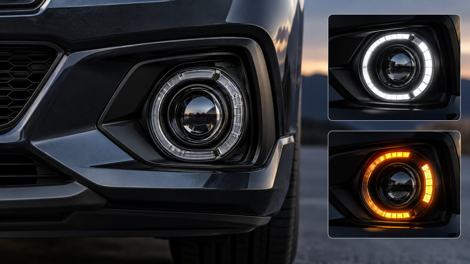
A compact front-bumper module that combines a fog lamp, a daytime running lamp (DRL), and an amber direction indicator can simplify packaging and create a consistent lighting signature. For aftermarket brands and OEM/ODM buyers, however, a three-function module is more than a cosmetic upgrade: it is a set of independently controlled lighting functions sharing limited optical, thermal, electrical, and sealing space.
The engineering challenge is to keep each function recognizable and reliable. The fog beam must meet its intended photometric and glare-control requirements; the white DRL must remain visible without masking the amber turn indication; and a sequential indicator must follow the timing and installation rules applicable to its target market. Meanwhile, heat from several LED groups and a larger harness must be managed within a low-mounted enclosure exposed to road splash and vibration.
This guide examines a 3 in 1 LED fog light DRL architecture from a B2B sourcing perspective. It explains optical separation, priority logic, compact thermal design, multipin waterproof connectors, and the evidence buyers should request before specifying a vehicle-specific or universal assembly. No one schematic, brightness percentage, connector pinout, or certification claim applies to every vehicle or market.
Table of Contents
3-in-1 Fog Lamp Engineering at a Glance
QUICK GUIDE
01
Optical Integration & Light Guides
Separate beam-forming and signaling zones.
02
Signal Priority & Control Logic
Validate vehicle and market-specific priorities.
Control the complete heat path.
04
Multipin Harness & Waterproofing
Specify and test the assembled interface.
Request product-specific validation evidence.
1. Optical Integration: Fog Beam, DRL, and Sequential Indicator
Three different lighting jobs require different optical distributions. A front fog lamp is designed to illuminate the near-road area with controlled upward light, whereas a DRL is intended to make the vehicle conspicuous in daylight. An amber turn signal must be unmistakable during its flash cycle. Putting all three functions behind one lens does not make their photometric requirements interchangeable.
Separate the beam-forming and signaling zones
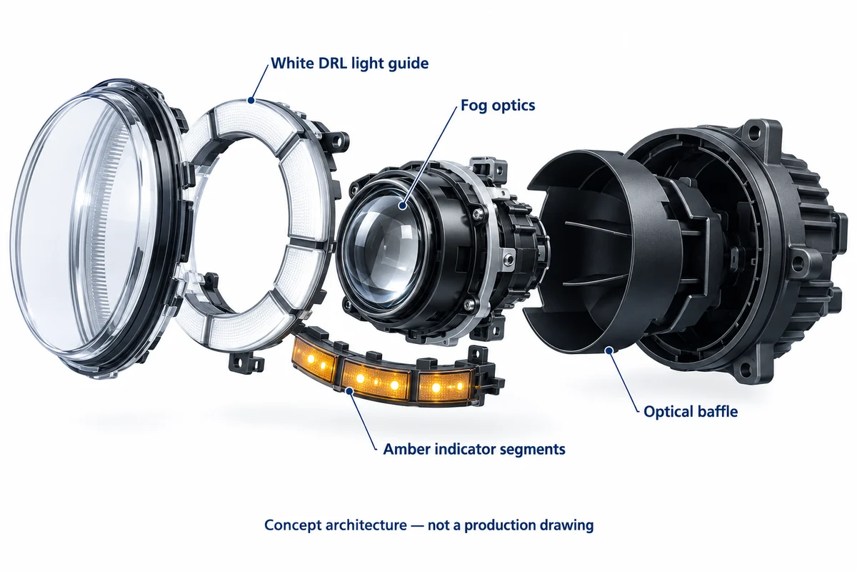
A practical concept uses a dedicated fog-light reflector or projector in the central cavity and a perimeter light guide for DRL and indicator functions. A PMMA or other qualified light-guide material can distribute LED light around a compact ring, while extraction features and diffusers help manage bright spots. The physical arrangement is only a design option: optical tooling, source position, color stability, temperature, and vehicle mounting height still require validation.
- Fog-light channel: evaluate beam spread, cutoff or glare-control characteristics, aiming provision, and applicable front-fog-lamp requirements.
- DRL channel: verify white-light intensity, uniformity, illuminated area, and vehicle-level placement under the intended market rules.
- Amber direction-indicator channel: validate color, visibility angles, flash operation, and any permitted sequential activation pattern; do not assume that an attractive sweep animation is automatically road-legal.
Optical crosstalk deserves particular attention. A white DRL that remains visible behind the amber indicator can reduce signal contrast, while internal reflections or light leaking between chambers may make the intended signal harder to distinguish. Optical baffles, separated emitters, controlled driver outputs, and targeted viewing-angle measurements help resolve these interactions.
For UNECE markets, manufacturers should assess the applicable UN R149 road-illumination provisions for the fog function and UN R148 light-signaling provisions for DRL and indicator functions, together with installation requirements such as UN R48. In the United States, evaluate FMVSS No. 108 and relevant SAE requirements. Approval or compliance must be established for the actual configuration and market, not inferred from the appearance of the assembly.
2. Driver Control and Signal-Priority Logic
The central controller should treat fog lighting, white DRL output, and amber turn indication as separate states with clearly defined priorities. Inputs may be discrete vehicle signals or outputs from a dedicated vehicle interface, depending on the platform. The control system must avoid unintended flicker, color mixing, unsafe behavior during startup, and unpredictable operation under low or transient voltage.
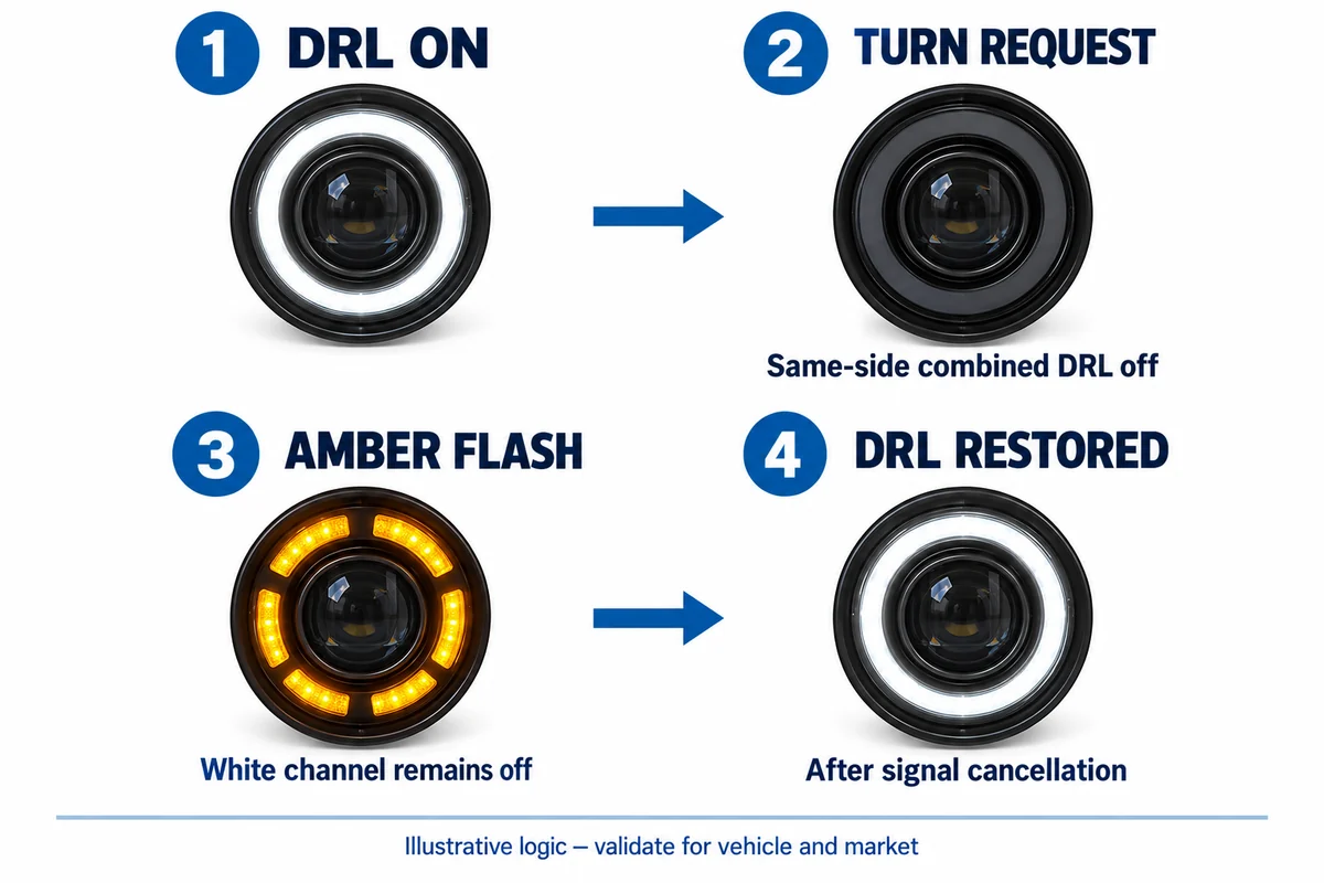
An especially important rule applies when the DRL is optically combined with a turn signal. Under the US FMVSS No. 108, the combined DRL must be deactivated on the affected side during turn or hazard activation and restored afterward. Other jurisdictions have their own requirements; therefore, a fixed rule such as “dim every DRL to 30% when headlights turn on” is not a universal design specification.
Illustrative state-priority matrix
| Vehicle condition | Fog channel | White DRL channel | Amber signal / validation focus |
|---|---|---|---|
| Daytime, no turn request | As commanded and legally permitted | Enabled when permitted | Off; verify normal DRL operation |
| Turn requested on left side | Independently controlled | Suppress left combined DRL where required | Left amber flashes; verify priority and optical contrast |
| Hazard warning active | Independently controlled | Suppress combined DRL channels where required | Both amber indicators follow required timing |
| Headlamps or position lamps active | Per vehicle controls | Off or transition only as legally permitted | Do not hard-code a universal percentage |
| Signal canceled | No unintended state change | Return to legal preceding state | No residual amber/white color mixing |
| Wiring fault or voltage transient | Defined safe response | No unintended oscillation | Record diagnostic and failure behavior |
Sequential indication introduces further constraints. The controller must manage activation duration, the visible sequence, synchronous turn-signal operation, and recovery after each flash. Test the complete lamp under all relevant states; a bench animation alone cannot establish legal compliance.
Claims of “CAN-bus error-free” operation should be avoided unless the exact target vehicle and control system have been tested. Warning lamps, lamp-out diagnostics, hyper-flash, and pulse-width-modulated supply behavior differ by OEM and model year. A universal resistor or decoder cannot be assumed to resolve them safely; the integration method must also account for heat, electrical protection, and vehicle warranty implications.
3. Compact Thermal Management and Driver Reliability
Multiple LED groups and driver circuits increase local heat concentration. Even where the fog, DRL, and indicator channels do not run at full output simultaneously, the designer must evaluate worst-case legal operating combinations, high ambient temperature, restricted airflow behind the bumper, and heat transferred from nearby vehicle components.
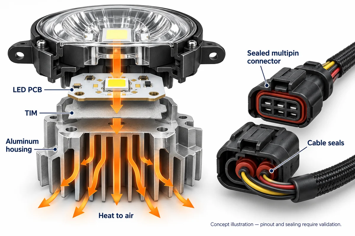
A practical thermal model follows the LED junction through its package and solder connection, PCB or thermal substrate, thermal interface material (TIM), metal housing, and surrounding air. Reducing resistance at one interface is useful only when the complete heat path is controlled. DTP copper designs, aluminum-core MCPCBs, and die-cast or extruded aluminum housings are options rather than guaranteed performance levels.
- Optical-electrical zoning: place hot fog-light emitters so their heat does not unnecessarily elevate DRL and indicator driver temperatures.
- TIM and mechanical contact: specify controlled interface thickness, clamp force, flatness, and material aging performance.
- Housing and cooling fins: evaluate dust accumulation, splash paths, bumper airflow, and the real heat-transfer area available after installation.
- Temperature monitoring: consider LED-board or driver-board sensors and a calibrated current-reduction strategy when component limits require protection.
An NTC thermistor or another temperature sensor can support thermal foldback, but neither an 85°C board threshold nor a particular junction-temperature target is universal. Qualification should define allowable component temperatures, functional behavior, and any reduction in optical output over the required ambient and voltage ranges.
For a buyer, the strongest evidence is not a stated copper conductivity number. It is an instrumented test showing temperatures at defined measurement points, stabilized light output, and correct operation of all three functions across the agreed duty cycle. Also request evidence that electronic protections do not disrupt the amber signaling function.
4. Multipin Harnesses and Waterproof Integration
An integrated module usually requires more signal separation than a conventional two-wire fog lamp. Some designs use a shared ground and individual inputs for fog, DRL, and turn; others employ control electronics, additional feedback, or dedicated vehicle interfaces. Connector cavity count and pin assignment must therefore be drawn from the approved design, not a generic four-pin diagram.
For example, a four-circuit concept could allocate common return, fog power, DRL command, and amber signal. This is an illustrative architecture only. Before production, confirm polarity, current capability, fused protection, connector keying, terminal retention, service access, and compatibility with the target vehicle harness. H11 and 9006 refer to common bulb-related interfaces and cannot be presumed to provide a complete multi-function connector solution.
Connector and system qualification matrix
| Interface / risk | Design evidence to request | Acceptance decision |
|---|---|---|
| Pinout and vehicle fitment | Approved drawing, mating connector part numbers and harness schematic | Match the named vehicle and variant |
| Electrical loading | Current draw, inrush, reverse-polarity and load-dump test plan | Within vehicle and driver limits |
| Sealing and drainage | Connector seal details, housing gaskets, vent placement and assembled-unit tests | Meets defined exposure profile |
| Optical function interaction | Photometric reports for fog, DRL and indicator in relevant modes | No masking or prohibited behavior |
| Environmental durability | Vibration, thermal cycling, corrosion and connector retention records | Meets agreed project criteria |
| Production consistency | End-of-line functional test, traceability, change-control records | Results tied to actual lots |
An IP rating applies to a tested item under specified conditions; it cannot be inherited automatically from a connector catalog. If IP67, IP68, or high-pressure washdown resistance is required, request evidence for the assembled enclosure and relevant interfaces under the defined test method. The supplier must also assess pressure cycling, cable entry seals, and the effect of cleaning chemicals or mud.
An appropriately selected ePTFE vent may help equalize enclosure pressure and manage moisture, but does not guarantee zero condensation or automatic IP69K performance. Vent part selection, position, airflow, and the total sealing system require their own validation.
5. B2B OEM/ODM Sourcing and Validation Checklist
Before requesting tooling or approving mass production, the buyer should agree on the exact combination of vehicle fitment, target markets, optical functions, wiring, operating modes, and qualification evidence. Use the following checklist in supplier RFQs and sample reviews.
- Confirm the target vehicle models, bumper geometries, left/right variants, mechanical tolerances, and installation drawings.
- Request separate photometric and signaling test plans for the fog, DRL, and sequential indicator functions, including the applicable regulatory editions and market.
- Review a state-transition matrix covering turn-signal priority, hazards, headlamp status, startup, restart, power loss, and fault recovery.
- Validate LED color consistency and light-guide uniformity at relevant viewing angles and thermal operating points.
- Check worst-case heat soak, thermal sensors, driver protections, electrical transients, EMI/EMC, and photometric stability.
- Obtain the approved mating connector, harness schematic, pin assignment, cable seal design, and tested ingress-protection conditions.
- Perform vehicle-specific diagnostic checks; never accept “CAN-bus compatible with all cars” as a substitute for evidence.
- Agree on sample approval, production inspection records, engineering-change control, warranty criteria, and responsibility for regulatory documentation.
A useful RFQ asks the supplier to identify which functions are proven by existing reports, which require new validation, and which features depend on the OEM vehicle controller. This makes cost, lead time, and approval risk visible before the brand commits to volume orders.
Frequently Asked Questions
Q1. What is the main advantage of a 3 in 1 LED fog light DRL assembly?
It combines three visual functions within one bumper location and can reduce the need for separate housings or styling features. However, savings in installation or sourcing depend on the vehicle and harness design. A robust program validates optical performance, signal priority, thermal load, and regulatory acceptance for each function.
Q2. Can the white DRL and amber sequential indicator use the same light guide?
They can share part of a light-guide architecture if the emitters, colors, optical extraction, and control strategy are designed appropriately. When a DRL is optically combined with a turn signal, the white channel may need to turn off on the signaling side. The actual requirements depend on the intended market and installation.
Q3. Does the DRL always dim when the fog lamp or headlamps turn on?
No. A fixed 30% or 50% output rule is not universally correct. The vehicle and market may require the DRL to switch off or operate in a separately approved position-lamp mode. The specification should reference the applicable legislation and define verified state transitions rather than an arbitrary brightness percentage.
Q4. Will an integrated fog lamp always work without CAN-bus warnings?
No. Compatibility depends on the vehicle’s lamp monitoring, electrical topology, pulse-width-modulated signals, and diagnostic thresholds. Buyers should test the exact make, model, and model year, including startup, hazards, faults, and thermal operation. Avoid assuming that a generic decoder or load resistor is suitable for every application.
Q5. Are four pins enough for fog, DRL, and turn-signal functions?
Sometimes, but not necessarily. A common-return design may use four circuits, while other systems need separate grounds, control, diagnostics, or a specific OEM interface. Pin assignments are product-specific. The correct connector is the one documented in the approved harness design and verified for current, mating, environmental sealing, and service conditions.
Q6. How can NVEL support a B2B multifunction fog-lamp project?
NVEL can discuss product and sourcing requirements, help coordinate fitment and customization specifications with manufacturing partners, and support sample and documentation requests appropriate to the project. Buyers should request product-specific evidence for optical functions, electrical integration, environmental testing, and certification rather than assuming every proposed configuration is already approved.
Conclusion
A multifunction LED fog lamp is successful only when the fog beam, daytime running light, and amber indicator remain individually effective within a shared enclosure. Robust design links optical separation to market-specific signal priority, validated thermal performance, a correctly specified harness, and realistic water-ingress protection.
For OEM/ODM buyers, the most useful purchasing decision is based on verified operating states and product-specific reports—not generic “plug-and-play,” “error-free,” or “fully certified” claims. Explore NVEL’s automotive lighting range and contact the team to discuss project-specific sample requirements, customization options, and validation evidence.
Discuss Your Multifunction Fog-Lamp Project
Explore NVEL’s automotive lighting range and discuss project-specific sample requirements, customization options, and validation evidence.
Related Technical Guides
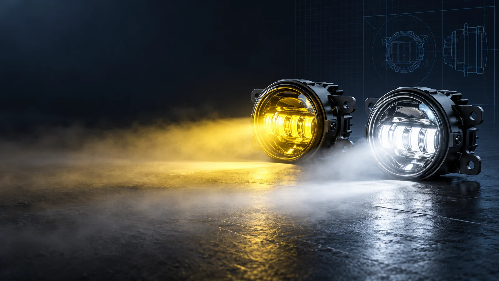
Technical Guides · LED Fog Lights
Dual-Color LED Fog Lamps: Optical Engineering, Circuit Switching, and Severe Weather Penetration
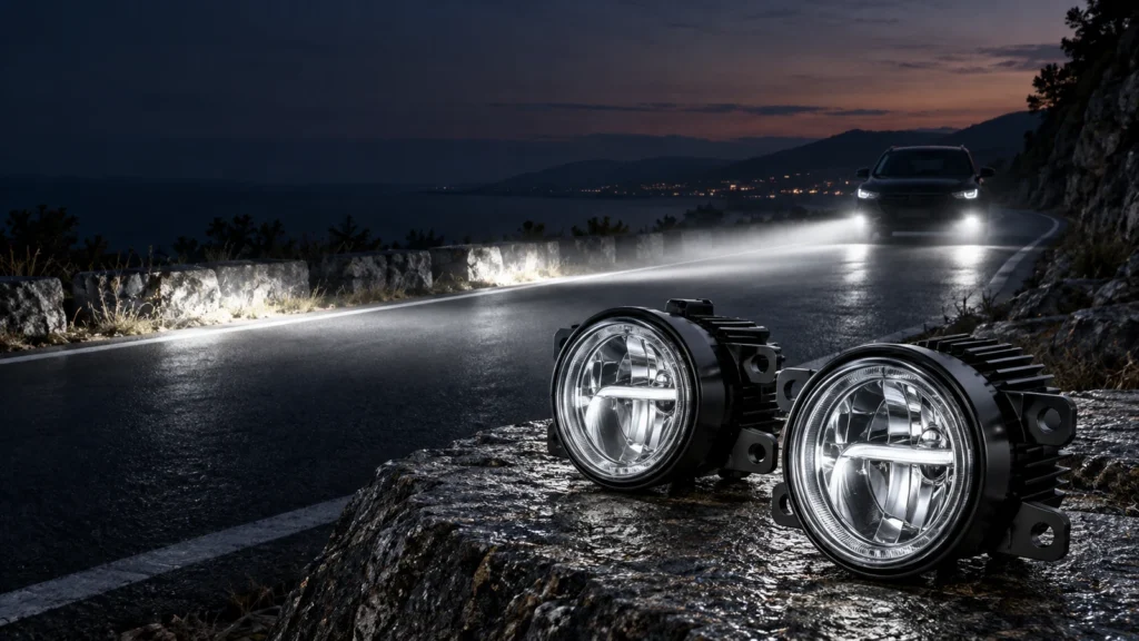
Technical Guides · LED Fog Lights
SAE J583 FOG LIGHT & ECE R19 Fog Lamp Compliance: Optical Cutoff and Wide-Beam Dispersion
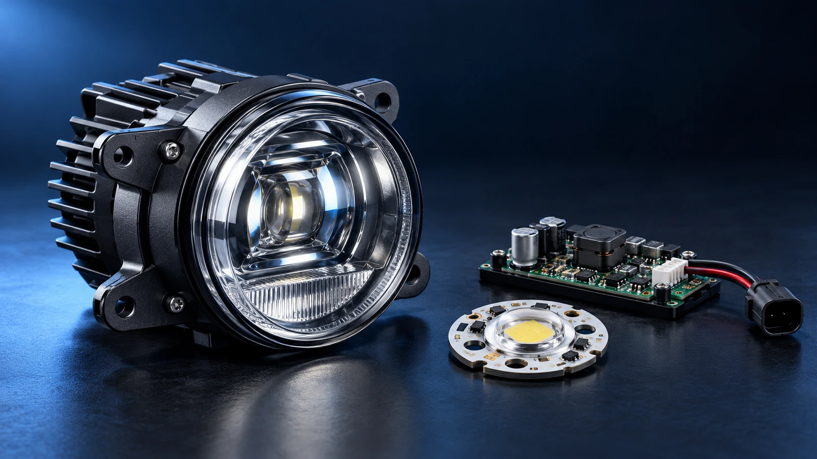
Technical Guides · LED Fog Lights