
TECHNICAL GUIDES · LED OFF-ROAD LIGHTS
Engineering Combo-Beam LED Work Lights for Off-Road Vehicles: Optical Layout, Beam Balance, and Photometric Validation
Optical zoning, installation geometry, and repeatable sample validation
October 29, 2026 · 10 min read
Introduction
A combo-beam LED work light is intended to provide more than one useful lighting zone from a single fixture: stronger forward intensity for distance awareness and broader illumination for the nearby ground, shoulders, or work area. For off-road vehicles and heavy-duty fleets, the engineering challenge is not simply to place spot and flood optics in one housing. It is to make their distributions work together after the lamp is assembled and installed on the vehicle.
Poorly coordinated optical zones can produce an intense central hotspot, an over-bright foreground, weak peripheral coverage, or visible dark bands between modules. The result may look powerful in a product photograph while performing unevenly in the actual operating environment. A useful design process therefore considers the optical layout, the transition between distributions, vehicle mounting geometry, and measured photometric performance.
This guide focuses on the engineering and validation of a combo beam led work light for off-road and work-vehicle applications. It does not replace a general explanation of spot, flood, and combo beam choices; for that broader overview, see NVEL’s existing off-road beam-pattern guide.
Table of Contents
Combo-Beam Engineering at a Glance
QUICK GUIDE
Coordinate forward-intensity and peripheral optical zones.
Evaluate hotspots, overlap, and smooth transitions.
Validate aiming and coverage on the intended vehicle.
Compare distributions under repeatable test conditions.
Tie approval criteria to the exact sample revision.
Designing the Optical Zones in a Combo-Beam LED Work Light
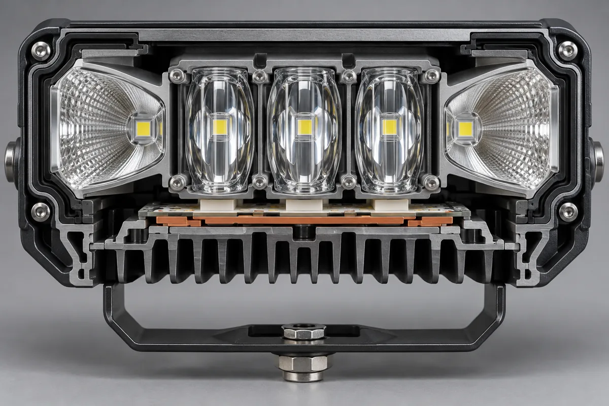
A combo-beam fixture combines optical elements intended to serve different parts of the field of view. One zone may concentrate more luminous intensity toward the forward distance, while another spreads light across nearer ground or the sides of the vehicle. The arrangement can use separate lens modules, reflector sections, TIR optics, or a hybrid design. There is no single layout that suits every housing, LED package, or application.
The optical system must be designed as a complete assembly. LED emitting-area size and position, optic geometry, module spacing, reflector finish, front-cover material, sealing features, and thermal conditions can all affect the final distribution. Changing an LED package or moving an optic by a small amount may change the beam, so the approved optical configuration should be treated as a controlled part of the product design.
| Design zone | Engineering objective | What to evaluate |
|---|---|---|
| Forward-intensity zone | Provide useful intensity at the target distance | Peak intensity, beam direction, and the intended task distance |
| Near-field fill zone | Illuminate the ground and nearby obstacles without excessive foreground brightness | Illuminance close to the vehicle and across the working width |
| Transition / overlap zone | Blend distributions so the combined field does not contain distracting dark bands or abrupt brightness changes | Horizontal and vertical photometric maps; overlap between adjacent optical modules |
| Mechanical interface | Keep the intended beam alignment stable on the vehicle | Bracket stiffness, adjustment range, fasteners, vibration exposure, and assembly tolerances |
A common design concept places higher-intensity optics near the center and wider-distribution optics toward the sides. This is only one possible arrangement, not a universal rule. A compact pod, a long light bar, and a multi-row array may require different zoning. The correct design is the one that meets the agreed field-coverage requirements when measured in its final configuration.
Beam Balance: Hotspot, Foreground Fill, and Transition Zones
The main challenge in a combo-beam work light is balance. A high central peak can improve distance visibility but may make the nearby ground disproportionately bright. Broad side fill can improve awareness of shoulders and obstacles, but poorly controlled spill may waste output outside the useful field. The target is not maximum brightness at every point; it is a distribution that supports the task without distracting extremes.
Evaluate the combined pattern rather than judging each optic in isolation. Adjacent modules should overlap enough to avoid unwanted gaps, but their peaks should not create an unnecessarily narrow band of excessive intensity. Review both horizontal and vertical distribution: a lamp may appear wide from the front while leaving weak coverage at the near-field edges or above and below the intended target area.
Use photometric maps and defined measurement points to compare prototypes. Record the test distance, target-plane orientation, input voltage, thermal condition, and the method used to define beam width. Beam-angle values are not always directly comparable between suppliers because the measurement threshold and reporting method may differ. Avoid treating a single nominal angle or an arbitrary spot-to-flood percentage as proof of good performance.
For B2B comparison, ask suppliers to provide a photometric distribution or isocandela / isolux plot for the exact model and optic configuration. Where relevant, compare peak intensity, illuminance at agreed points, useful horizontal coverage, and the continuity of the transition between central and peripheral zones. Raw lumen output alone cannot show whether the light reaches the intended locations.

Vehicle Mounting Geometry Changes the Result
A combo-beam work light does not operate in a laboratory coordinate system once it is mounted. Installation height, bracket angle, vehicle pitch, bodywork, bumper or roof-rack position, and the lamp’s distance from the vehicle centerline can all change where the beam lands. A distribution that works well on a test stand may illuminate the wrong area if the mounting position is different from the design assumption.
Define the intended installation before approving a sample. Document the mounting location, nominal aiming angle, adjustment range, nearby obstructions, supply voltage, and the vehicle’s expected operating posture. For equipment that pitches or moves under load, test representative positions rather than relying on a single static view. Confirm that the bracket holds its setting after the specified vibration and handling checks.
Combo-beam auxiliary work lights should be evaluated for their intended off-road or work-zone use. They should not be assumed to replace a road-legal headlamp or driving lamp; road-use requirements depend on the lamp’s purpose, approval status, vehicle installation, and applicable market rules.
A practical installation check should include the driver’s view, nearby ground coverage, side visibility, glare to nearby operators, and reflections from the vehicle or equipment. Photographing the beam can help document a setup, but photos alone are not a substitute for controlled photometric measurements.
Photometric Validation for a Combo-Beam LED Work Light
Photometric validation turns a visual claim into comparable evidence. Lumens describe luminous flux emitted by the source or lamp under a stated measurement method; candela describes luminous intensity in a direction; lux describes illuminance arriving at a surface. These measures answer different questions. A high lumen figure does not, by itself, demonstrate useful distance performance or even coverage.
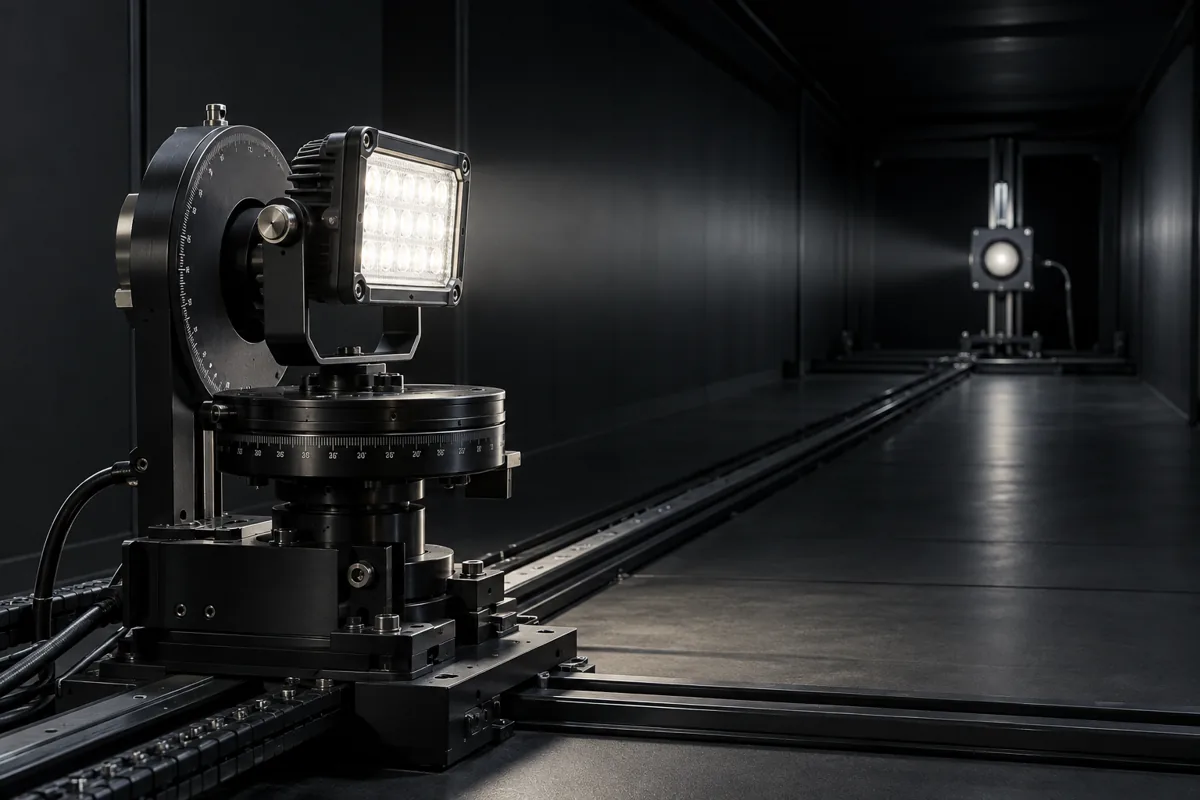
For a combo-beam design, the validation plan should match the intended task. Depending on the application, it may include a photometric distribution measured on a goniophotometer, illuminance readings at specified points on a target plane, horizontal and vertical coverage, and an assessment of the central-to-peripheral transition. If a distance or minimum-lux claim is used, it should be tied to a stated threshold and a traceable measurement method rather than presented as a universal range.
Compare samples under controlled and repeatable conditions. Record the exact model and optic version, input voltage, current draw where relevant, ambient conditions, warm-up or thermal stabilization procedure, measurement distance, instrument setup, and test date. If optical parts, LED packages, drive current, front covers, or mechanical alignment change, determine whether the previous photometric evidence still represents the revised configuration.
The inverse-square relationship can help explain how illuminance changes with distance for an idealized point source in a defined direction, but real fixtures have extended sources and non-uniform distributions. Use measured data for product decisions instead of extrapolating a single candela value into a blanket performance promise. For a broader explanation of output metrics, see NVEL’s lumens-versus-lux guide.
OEM Sample Approval: What Buyers Should Verify
Before approving a combo-beam work light for volume production, B2B buyers should connect the optical target to a repeatable sample-approval process. The specification should identify the exact housing, LED and optic configuration, mounting hardware, electrical input, and any front-cover or accessory option that can affect the beam.
- Confirm the part number, optical configuration, supply-voltage range, connector, and mounting arrangement of the sample under review.
- Agree on the target field of coverage, required measurement points, test distance, and acceptance criteria before comparing samples.
- Request photometric plots or a measurement report tied to the exact model and optic version; confirm units, test conditions, and instrument method.
- Check the beam on the representative vehicle or mounting fixture, including near-field fill, forward reach, side coverage, and distracting bright or dark zones.
- Repeat key checks on representative samples to assess consistency rather than approving a single hand-selected unit.
- Validate thermal performance, vibration resistance, ingress protection, corrosion resistance, EMC, and other durability requirements according to the actual application and agreed specification.
- Record approved drawings, test reports, sample revision, and change-control expectations so that production units remain aligned with the approved configuration.
Not every project requires the same test list or pass threshold. Buyers and suppliers should agree on requirements before testing and avoid claiming compliance with a standard unless the standard applies to the specific product and the relevant test evidence is available. The goal is a traceable decision: the approved sample, its optical configuration, and its acceptance evidence should all refer to the same version.
Frequently Asked Questions
What does combo beam mean in an LED work light?
It describes a light distribution that combines more concentrated forward intensity with wider near-field or peripheral coverage. The actual pattern depends on the optical design and should be verified for the specific model.
Does every combo-beam light use a central spot optic and outer flood optics?
No. That is one possible layout. Other products may use different lens arrays, reflector geometries, or hybrid optical arrangements. Buyers should assess the measured distribution rather than assume a particular internal structure.
How can buyers compare two combo-beam work lights fairly?
Compare the exact model and optic configuration under comparable input, thermal, distance, and measurement conditions. Review the photometric map and agreed target points, not just advertised lumens or a beam-angle label.
Do higher lumens guarantee a longer useful beam?
No. Useful distance depends on how intensity is distributed, the target illuminance requirement, installation and aiming, atmospheric conditions, and the task. Ask for measured candela or illuminance evidence tied to a stated method.
Why does vehicle mounting affect the beam pattern?
Mounting height, aiming angle, bracket movement, vehicle pitch, and nearby bodywork change where the light lands and what the operator sees. Validate the lamp in a representative installation whenever possible.
What should an OEM buyer request before approving a combo-beam sample?
Request the exact model and optic revision, relevant photometric data, defined test conditions, installation details, and acceptance criteria. Add environmental, electrical, or durability tests where they are required by the application.
Conclusion
A well-engineered combo-beam LED work light is defined by how its optical zones perform together—not simply by the presence of spot and flood elements in one housing. Optical layout, beam overlap, vehicle mounting, and repeatable photometric validation determine whether forward intensity and near-field coverage meet the intended task.
For OEM and fleet programs, specify the target field of coverage, agree on measurable acceptance criteria, and approve the exact optical configuration using traceable sample data before production. This makes performance easier to compare and helps keep the delivered lamp aligned with the application.
Discuss Your OEM Work-Light Requirements
Explore automotive lighting products or contact our team to discuss the optical configuration, installation requirements, and sample acceptance criteria for your project.