TECHNICAL GUIDES · OPTICAL ENGINEERING
Reflector Optics vs. Projector Lenses in LED Fog Lamps: Beam Efficiency and Glare Suppression
Beam control, optical trade-offs and evidence-based OEM sourcing.
October 29, 2026 · 12 min read
Introduction
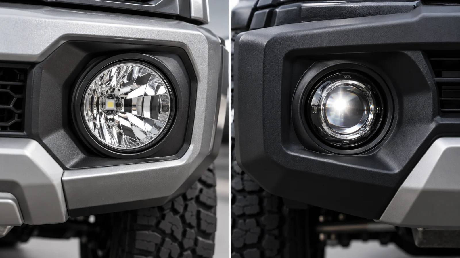
In automotive replacement programs, off-road accessory lines, and heavy-duty fleet applications, the optical system is one of the most important design decisions in an LED front fog lamp. Buyers often compare a compact free-form reflector against a projector module with a lens and, in some designs, a cutoff shield. Both approaches can create useful low-mounted illumination, but their performance depends on the complete optical design rather than the name of the architecture.
A well-controlled fog-lamp beam requires sufficient useful intensity across the intended road area while limiting unwanted upward light and glare. That balance is affected by LED source size, geometry, thermal stability, lens and reflector materials, aiming, and installation position. Projector optics can facilitate controlled transitions, while optimized free-form reflectors may offer excellent lateral spread without a bulky secondary lens; neither architecture is automatically more efficient or legally compliant.
This technical guide explains the engineering differences behind the LED fog light projector lens, reflector, and hybrid total-internal-reflection (TIR) options. It also provides a practical framework for reviewing photometric evidence, component durability, project cost, and market-specific approval requirements before committing to an OEM/ODM tooling program.
Table of Contents
Reflector, Projector and Hybrid Fog Lamp Optics
QUICK GUIDE
01
Optical Physics & Beam Metrics
Evaluate useful intensity, distribution and glare.
Review wide-beam design, coatings and packaging.
03
Projector Lens & Cutoff Design
Assess focus, shielding, materials and alignment.
Compare hybrid optics with measured evidence.
05
B2B Optical Sourcing Checklist
Define validation evidence before tooling.
1. Optical Fundamentals: Beam Distribution, Efficiency, and Glare
The optical task is to redirect light from an LED light-emitting surface into a specified angular intensity distribution. A bare LED emits into a broad solid angle; reflectors and lenses reshape that light through reflection, refraction, and sometimes total internal reflection. The resulting road pattern is not determined by lumens alone: a lamp with a higher source-lumen rating may still deliver less usable light in the regulated measurement zones.
Measure the finished luminaire, not a marketing claim
- Useful luminous intensity: review measured candela values at the specified horizontal and vertical angular test points, not just peak center lux.
- Beam width and foreground balance: assess whether the intensity distribution covers the intended near-road area without excessive foreground brightness or distracting hotspots.
- Above-cutoff light and stray glare: quantify the measured intensity in restricted upper regions; an attractive wall projection does not prove compliance.
- Optical system efficiency: define the metric and measurement boundary. LED package efficacy, luminaire output ratio, and useful-beam efficiency are different quantities.
- Aiming and tolerance: repeat measurements at realistic mounting positions, component tolerances, supply voltage, and operating temperature.
Ray-trace simulation is useful during development, but measured photometry from a production-representative lamp is the basis for approval decisions. Compare like-for-like input power, source binning, temperature, and measurement geometry. The blanket claims that reflectors always capture 60–70% while projectors exceed 85% are not reliable universal figures; published designs vary substantially with source and optical geometry.
For regulatory planning, SAE J583 addresses front fog lamps, including performance and test methods. UNECE UN Regulation No. 149 covers road illumination devices, including front fog lamps; the historical UN R19 and its Class F3 terminology remain relevant in legacy documents. Exact test points and approval routes depend on the adopted edition, market, and lamp category. Avoid equating a sharp visible cutoff with legal approval.
2. Free-Form Reflectors: Wide Distribution and Packaging Efficiency
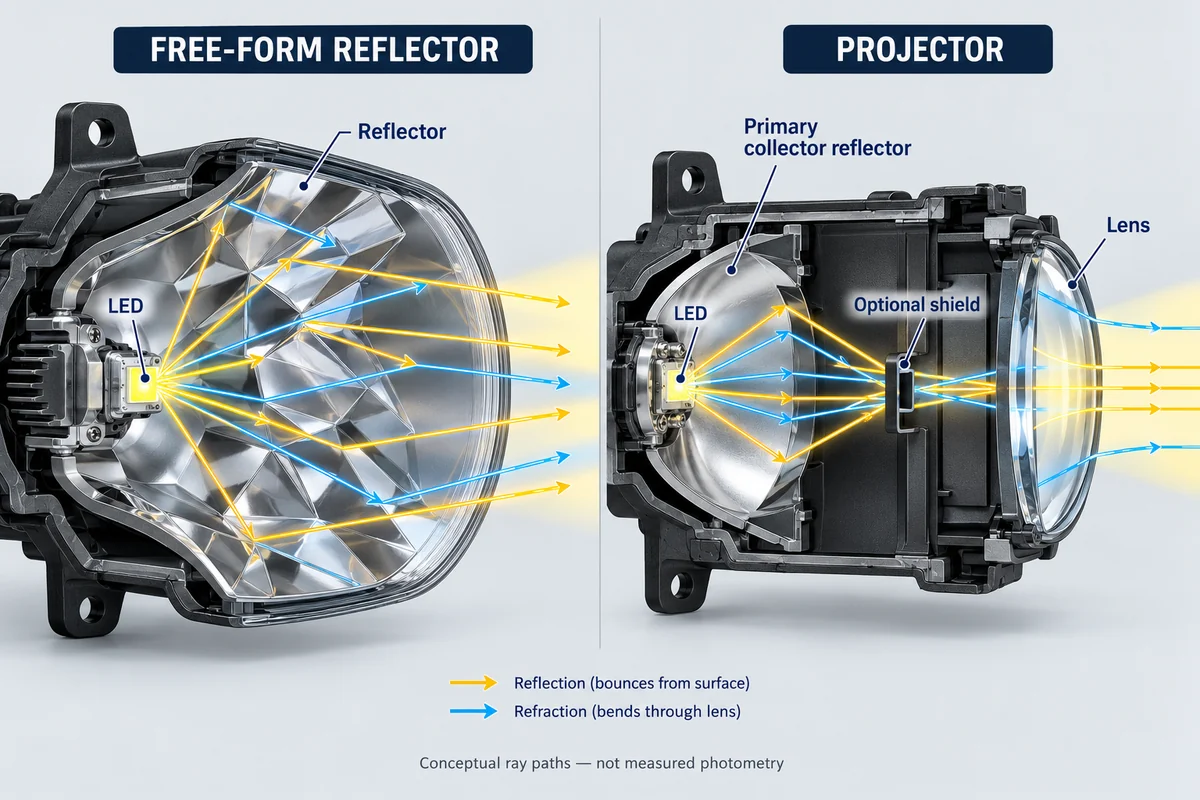
A free-form reflector controls light using computer-designed reflective facets or a smooth non-imaging surface. Instead of requiring a thick projector lens, the designer maps rays from the LED source onto desired angular zones. The reflective coating, source position, reflector shape, and front cover all influence the actual output.
Where reflector systems work well
- Wide horizontal coverage: a tuned reflector can direct light toward road edges and near-field zones, which can be useful for fog-lamp and low-speed auxiliary applications.
- Compact depth: omitting a conventional projector lens can simplify packaging in shallow bumper cavities, although reflector width may still be substantial.
- Cost and assembly: fewer precision lens parts can reduce the bill of materials, depending on tooling, metallization, sealing, and optical tolerances.
- Design flexibility: facets can be optimized for source placement, aiming and market-specific photometric targets; a reflector need not be a simple parabola.
A weakness of some reflector architectures is sensitivity to uncontrolled direct emission, LED source variation, or veiling reflections from the front cover. However, a carefully engineered free-form reflector can control upward light effectively. Describing all reflector fog lamps as inherently glaring or incapable of a compliant cutoff would be inaccurate.
Request a reflector coating specification and durability validation. Reflectance depends on substrate preparation, deposited aluminum or other coatings, protective overcoats, heat, humidity, and corrosion exposure. The value of a low-cost reflector disappears if coating degradation or mechanical alignment shifts the beam during service.
3. Projector Lenses: Cutoff Control and Optical Trade-Offs
A common LED fog light projector lens architecture uses a primary collector or reflector, an aperture or cutoff element where appropriate, and a refractive projection lens. Some modern compact modules use different condenser or direct-projection layouts. The lens redistributes the light leaving the internal optics and can make a carefully designed upper beam transition easier to reproduce.
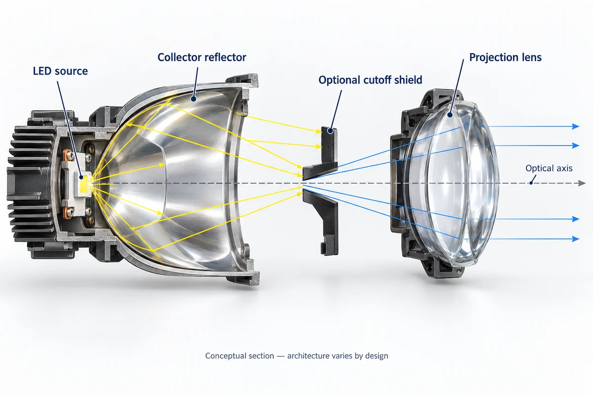
What the projector architecture can—and cannot—promise
The cutoff shield can remove selected upward rays, but it also intercepts some potentially useful light and may introduce thermal loads or internal reflections. Optical transmission through a lens is never perfect, and glare is not reduced to absolute zero. Real performance depends on LED placement, shield geometry, focus, lens quality, alignment, and the complete external cover.
| Engineering criterion | Free-form reflector | Projector with lens / cutoff |
|---|---|---|
| Typical optical approach | Source-to-faceted-surface redistribution | Primary collector, optional shield, projection lens |
| Horizontal coverage | Can be optimized for a broad spread | Can also be broad; dependent on prescription |
| Upper-light control | Through facet design, source management and baffles | Through optical prescription and optional shield |
| Packaging | Often shallower but may need lateral area | Lens and focal distance can increase depth |
| Optical losses | Reflective coating, direct-light and cover losses | Collector, shield, lens and cover losses |
| Tolerance sensitivity | LED position, facet shape and coating | LED, focal alignment, shield and lens position |
| Compliance evidence | Measured complete-lamp photometry required | Measured complete-lamp photometry required |
Optical glass may provide thermal stability and scratch resistance, while qualified PMMA or polycarbonate may reduce weight and enable molded surface features. No single material wins across all applications: optical transmission, UV exposure, stone-impact vulnerability, thermal expansion, environmental coatings, and proximity to the LED source all affect selection.
An LED projector may create a very distinct wall cutoff, yet overly concentrated light below that edge can create an uncomfortable near-field hotspot. For OEM purchasing, require the actual photometric plot rather than accepting a product photo with an apparently sharp horizontal line.
4. Hybrid and TIR Optics: Combining Compactness With Beam Control
Total internal reflection (TIR) optics combine refractive and reflective ray paths within a transparent optical element. Free-form TIR surfaces can collect portions of the LED emission and redirect them toward selected beam zones. Hybrid systems may also use reflective cups, baffles, segmented optics, or auxiliary microstructures to manage different angular portions of the output.
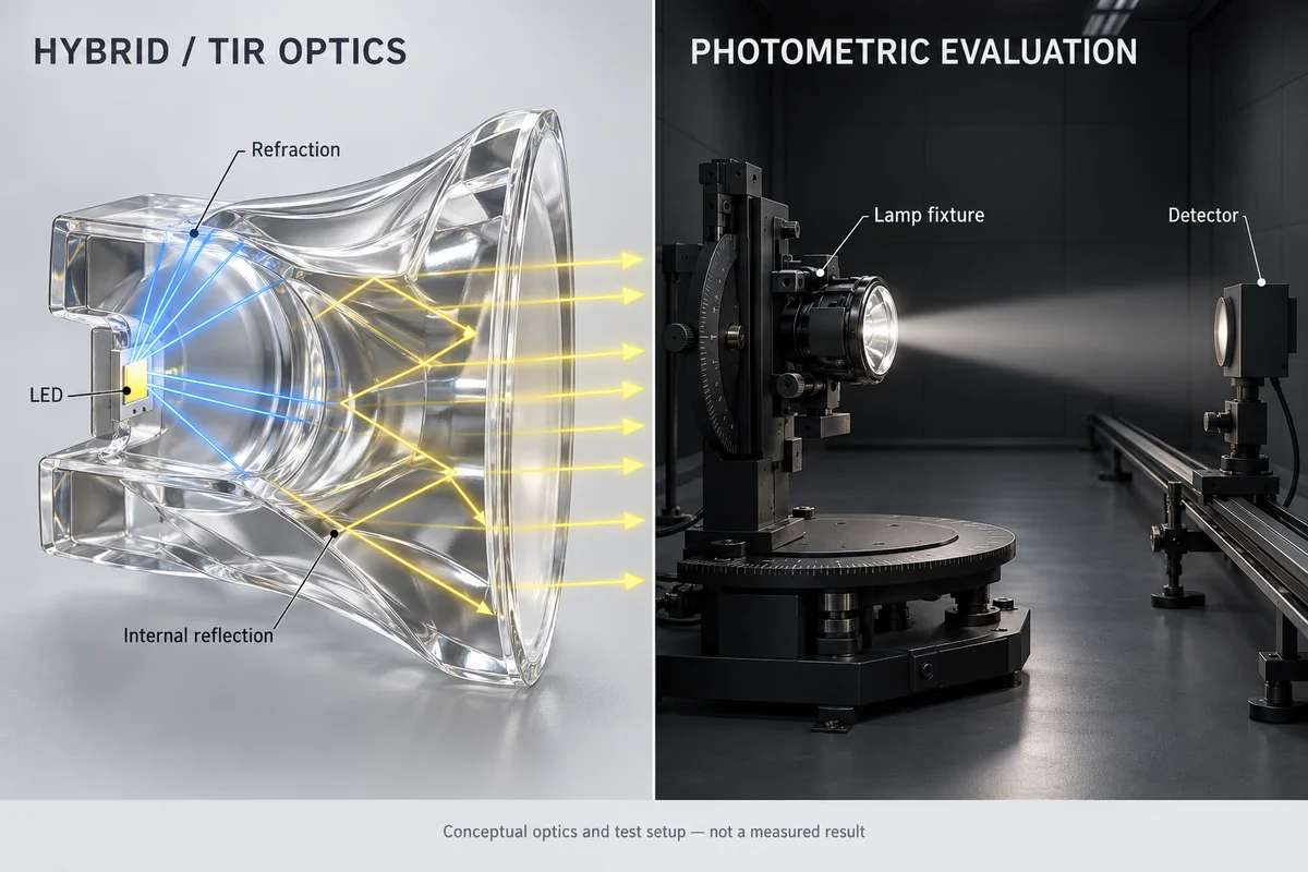
The appeal is design flexibility: a compact molded element can combine collection and shaping functions, sometimes reducing assembly parts. However, TIR behavior depends on refractive index, entry angles, temperature, manufacturing accuracy, surface cleanliness, and material stability. “95% light capture” or “over 90% efficiency” cannot be generalized from the term TIR alone.
Compare solutions with a measured validation matrix
| Validation item | Evidence to request | Purchasing decision |
|---|---|---|
| Photometric performance | Goniophotometer intensity table and beam plot at defined conditions | Pass/fail against intended market and usage |
| Glare control | Above-horizontal test points, cutoff profile, aiming sensitivity | Acceptable stray light at real installation angles |
| Optical efficiency | Input watts, luminaire flux and useful beam metrics with definitions | Compare delivered performance, not brochure percentages |
| Material aging | UV, thermal cycling, coating or haze tests as applicable | Stable optical properties over target life |
| Manufacturing repeatability | Prototype-to-pilot variation, LED placement and optical tolerance checks | Maintain approval margin in mass production |
| Fitment and durability | Dimensional checks, impact/vibration and ingress evidence | Compatible with target bumper and service environment |
Published optical-design studies demonstrate that both free-form reflector and hybrid TIR concepts can be engineered for front fog lamp requirements, with reported efficiencies tied to particular prototypes or simulations—not universal technology rankings. The most useful comparison therefore uses the same LED source family, mechanical envelope, test procedure, and performance target.
5. B2B Optical Sourcing Checklist for OEM/ODM Projects
Before approving tooling, sourcing teams should define the application and ask for evidence that the selected optical platform will deliver repeatable performance at the intended assembly cost.
- Identify the target market, vehicle category, installation height, aiming arrangement, and applicable front-fog-lamp standards or approval requirements.
- Request production-representative photometric tables and beam plots, with the test voltage, temperature and lamp orientation recorded.
- Compare useful beam distribution and glare-limited angles rather than relying on peak lumens, center lux, or illustrative cutoff photographs.
- Confirm lens or reflector material grades, coating durability, UV resistance, humidity performance and optical transmission test methods.
- Check alignment stack-up, bracket stiffness, focal tolerances and how optical components are retained under vibration and thermal cycling.
- Review package depth and width, airflow and heat management, seal integrity, cleaning resistance, and bumper or grille fitment.
- Agree on prototype approval, pilot-run measurement sampling, design change control, requalification criteria and traceable test reports.
- Confirm any claimed SAE, UNECE or other conformity is product-specific; obtain report identifiers and verify their applicability.
A well-structured RFQ asks suppliers to state what is already validated, what remains a design target, and whether regulatory evidence covers the exact optical assembly and market. This avoids costly tooling decisions based on attractive renderings or ambiguous compliance labels.
Frequently Asked Questions
Q1. Is an LED fog light projector lens always better in heavy fog?
No. Projector architectures can help control an upper transition, but actual visibility depends on the measured beam distribution, lamp aiming, mounting, weather conditions, and road environment. A properly designed reflector may also deliver effective glare-controlled fog illumination. Compare complete-lamp photometry, not the optical label.
Q2. Do reflectors always produce more glare than projectors?
No. Glare depends on upward stray light, source placement, reflector or lens prescription, front cover and installation alignment. Both designs can be optimized for restricted intensity above the intended beam. A shield is one tool for controlling light, not a guarantee of zero glare.
Q3. Which architecture is more energy efficient?
There is no reliable universal winner. A projector may lose light at a shield and lens, while a reflector may lose light at its coating and from uncontrolled direct rays. Well-designed hybrid or TIR modules can also be competitive. Ask for clearly defined optical-efficiency measurements and useful intensity at equal electrical input.
Q4. Are glass projector lenses better than PMMA lenses?
It depends on the design. Glass commonly offers thermal and scratch-resistance advantages; optical plastics may enable lighter, more complex molded shapes. UV aging, impact conditions, coatings, expansion and operating temperature must be verified for the application. Neither material automatically assures a longer lamp life.
Q5. Does a sharp cutoff prove SAE J583 or UN R149 compliance?
No. Compliance depends on the full set of applicable photometric, construction, installation or approval requirements, not a single beam-wall image. The buyer should request product-specific test data, applicable standard editions and approvals where required.
Q6. How can NVEL assist with reflector and projector fog-light sourcing?
NVEL can discuss project requirements, coordinate suitable manufacturing and customization options with partners, and support requests for samples, photometric evidence, material documentation and commercial quotations. Engineering resources, production processes and approvals should be confirmed for the specific supplier and product rather than assumed across the range.
Conclusion
A successful fog lamp uses its optical architecture to deliver the required road illumination with controlled stray light, repeatable aiming and practical manufacturing tolerances. Free-form reflectors, projector lenses and hybrid/TIR elements can all be viable when designed for the application; no technology automatically wins on optical efficiency, cutoff quality or legal approval.
For OEM and aftermarket brand owners, the decisive evidence is a complete-lamp photometric report, material and durability data, packaging fit, and traceable production qualification. Explore NVEL’s universal Bi-LED fog light projector range and contact the team with your target beam pattern, vehicle application and purchasing requirements to discuss suitable sourcing and customization options.
Discuss Your Fog Lamp Optical Requirements
Explore NVEL’s automotive lighting range and share your beam pattern, fitment and purchasing requirements with our team.