TECHNICAL GUIDES · LED WORK LIGHT ENGINEERING
Electromagnetic Compatibility (EMC) in Industrial & Off-Road LED Lights: CISPR 25 Class 3 vs. Class 5
Conducted and radiated EMI, engineering controls and traceable laboratory evidence.
October 29, 2026 · 10 min read
Introduction
Industrial and off-road LED work lights are routinely installed close to two-way radios, GNSS receivers, vehicle displays and telematics modules. On mining trucks, tractors, utility fleets and overland vehicles, a lighting upgrade that appears mechanically compatible can still create electrical noise that degrades radio reception or complicates system integration.
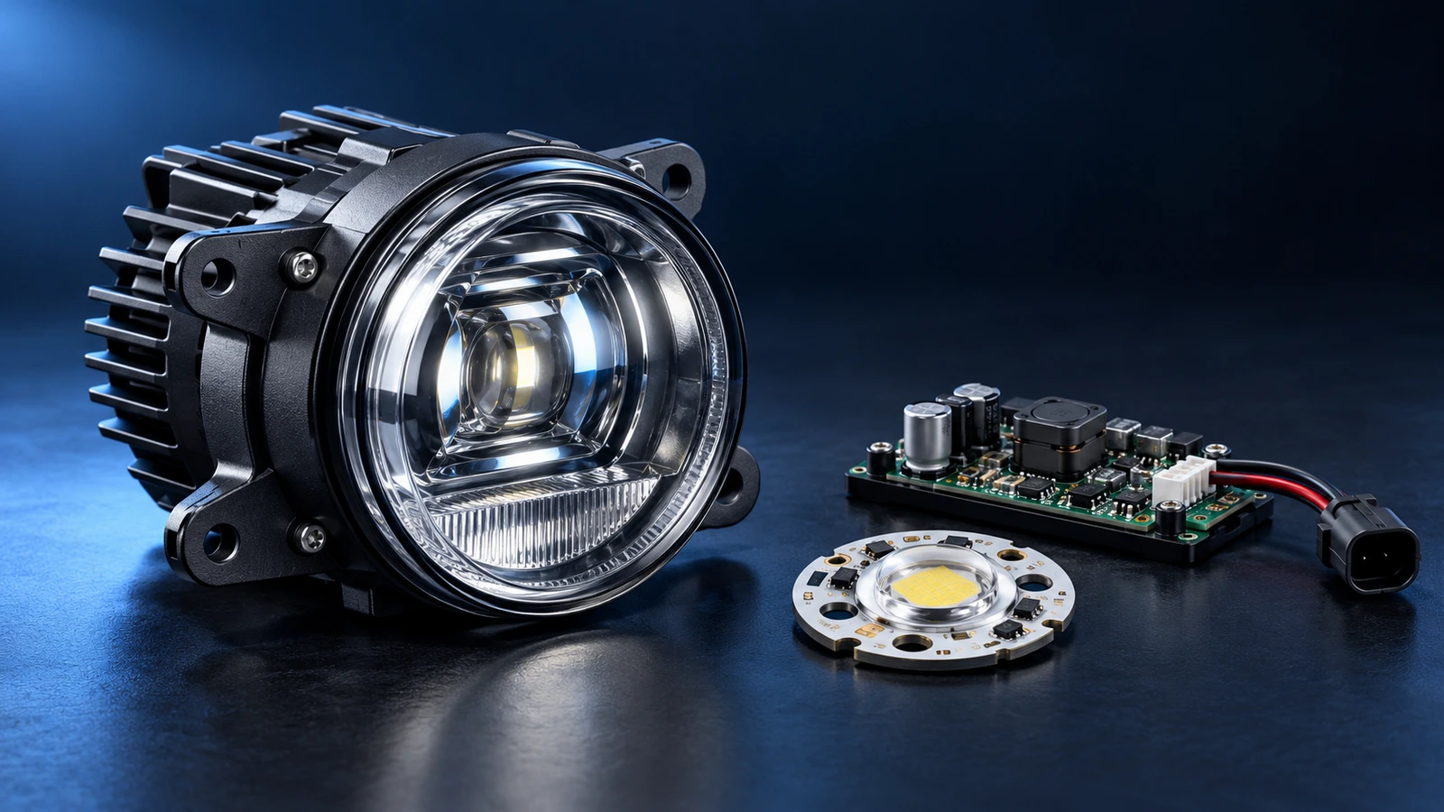
The principal concern is often the switched-mode LED driver rather than the LED emitter itself. Fast voltage and current transitions inside a buck, boost or buck-boost circuit can couple through the supply harness or radiate from PCB structures and cables. Poor grounding and installation-specific wiring can amplify the effect. A quiet-looking lamp on the bench is not necessarily quiet in the vehicle.
For an OEM buyer or aftermarket brand, a meaningful cispr 25 led work light specification begins with a documented emissions target, a repeatable test setup and traceable results for the exact lamp configuration. This guide explains where interference originates, what Class 3 and Class 5 mean, which design measures are worth reviewing and how to audit evidence before placing a production order.
Table of Contents
CISPR 25 LED Work Light Engineering
QUICK GUIDE
01
Sources of EMI in LED Drivers
Trace conducted and radiated coupling paths.
02
CISPR 25 Class 3 vs. Class 5
Compare methods, bands, detectors and evidence.
03
Filtering & Housing Shielding
Review layout, filters and enclosure interfaces.
Check the exact tested lamp configuration.
Request traceable qualification documents.
1. How LED Drivers Generate Conducted and Radiated EMI
A constant-current LED driver often switches power devices at high frequency. Fast edges produce a spectrum containing the switching fundamental and harmonics; the observed emissions also depend on switching-node geometry, parasitic capacitance, inductor construction and the return-current path. PWM dimming can introduce another modulation component. No single switching-frequency range describes every LED work-light design.
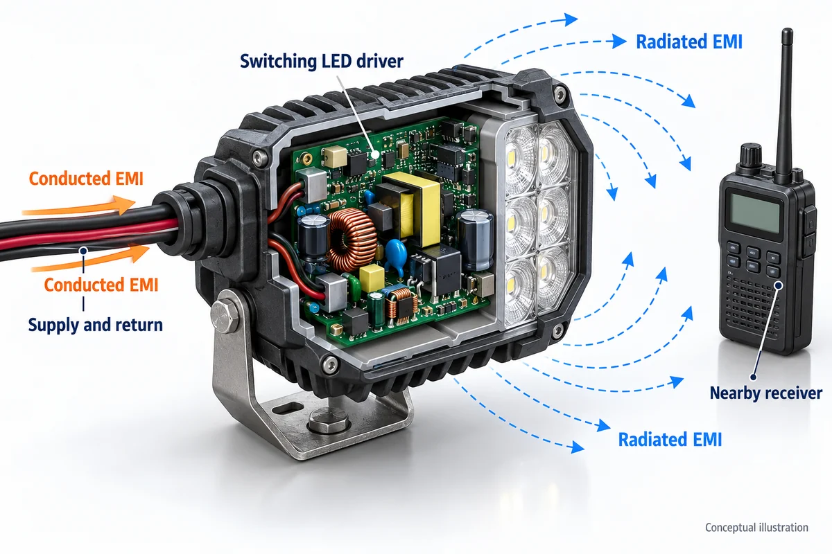
Conducted emissions travel along the DC supply and return conductors. Differential-mode noise appears between the power lines, while common-mode currents can flow together along a harness relative to other structures. That same harness can become an efficient radiating element. Radiated emissions may also couple from switch nodes, inductor fields, enclosure seams or poorly controlled cable exits.
Three coupling paths to investigate
- Power input and return: High-frequency ripple can reach nearby receivers through shared power distribution and cable routing.
- Switch node and magnetics: Large high-di/dt loops and exposed magnetic fields can create near-field coupling that later becomes radiated noise.
- Installation and chassis: Harness length, routing, vehicle metalwork, lamp mounting and return connections can change the measured result.
Radio static is a common field symptom, but the symptom alone does not identify the source. Suspected GPS or network disruption needs a separate vehicle-level investigation; CISPR 25 emissions testing should not be represented as proof of CAN-bus immunity or complete functional safety.
2. CISPR 25 Class 3 vs. Class 5: What Buyers Should Compare
CISPR 25:2021 is an IEC/CISPR standard for radio-disturbance limits and measurement methods intended to protect receivers installed on vehicles, boats and related equipment. It addresses conducted and radiated emissions. The edition, frequency bands, method, detector, harness configuration and agreed limit class matter when interpreting a report.
For measurement categories offering limit classes, Class 5 typically sets more stringent emissions limits than Class 3. However, neither class is a universal product label, an automatic legal approval or a promise of zero interference in every vehicle. A supplier should state exactly which test methods and frequency bands achieved the quoted class.
| Review point | Class 3 target | Class 5 target | Evidence a buyer needs |
|---|---|---|---|
| Relative emissions requirement | Less stringent than Class 5 for a comparable method | More stringent for a comparable method | Exact CISPR 25 edition and applicable limit-table reference |
| Conducted measurements | Compare emissions with agreed Class 3 lines | Compare emissions with agreed Class 5 lines | Method, power setup, impedance network, detector and measured traces |
| Radiated measurements | Compare against the applicable Class 3 radiated limits | Compare against the applicable Class 5 radiated limits | Antenna setup, chamber method, harness routing and measured traces |
| Procurement statement | Only for methods and bands actually passed | Only for methods and bands actually passed | Signed report identifying tested sample, configuration, margins and deviations |
A blanket claim such as “CISPR 25 Class 5 compliant” is incomplete without context. Ask whether it covers conducted emissions, radiated emissions or both, and request the full spectral plots with limit lines and pass/fail margins. Avoid copying isolated dB figures from an unrelated edition or detector into a product datasheet.
CISPR 25 should also be distinguished from radiated-immunity standards such as ISO 11452-2. Emissions testing asks how much disturbance the lamp produces; immunity testing asks how the lamp behaves when exposed to specified external RF fields. Both may matter in an OEM qualification plan, but they answer different questions.
3. EMI Filtering, PCB Layout and Housing Shielding
There is no one-component shortcut to a quiet LED work light. A strong design starts with current-loop control and appropriate driver selection, then adds filtering or shielding where measurements show it is needed. Every change must be assessed for switching stability, temperature rise, surge tolerance and optical performance.
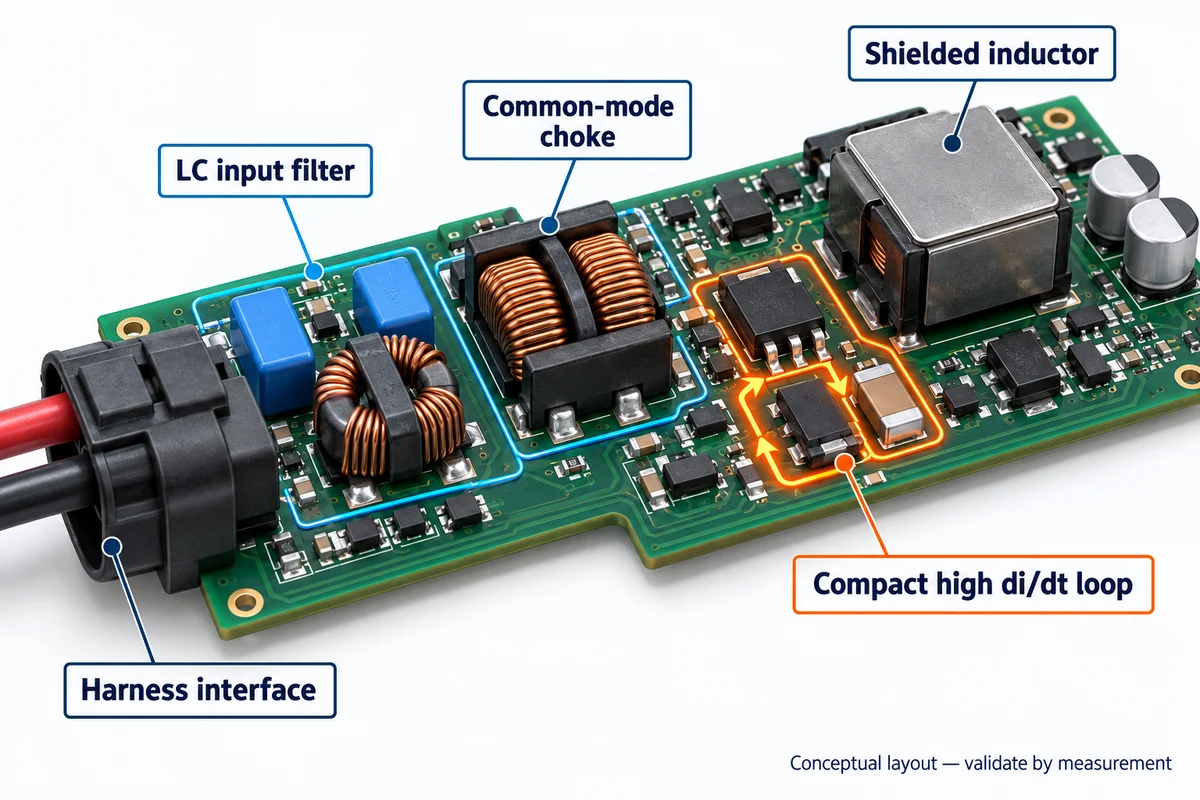
Engineering controls worth reviewing
- Input filtering: A differential-mode LC or pi filter can attenuate switching ripple; common-mode chokes may be added when common-mode currents dominate. Values and damping must be validated in-circuit.
- PCB routing: Keep high-di/dt loops small, place input bypass capacitors close to switching devices and maintain controlled return-current paths. Separate sensitive sensing traces from noisy nodes.
- Magnetic components: A suitably selected shielded inductor can reduce magnetic coupling, but the overall layout and filter response still determine test performance.
- Enclosure and cable interfaces: A metal housing may provide useful RF containment when seams, bonding, cable exits and return paths are designed appropriately. An aluminum casting alone is not an automatic Faraday cage.
- Switching strategy: Driver slew-rate control, snubbers or spread-spectrum techniques may reduce peak emissions, subject to efficiency, thermal and lighting-control trade-offs.
Chassis bonding is application-specific: some sealed auxiliary lamps operate with isolated electrical returns or mounting structures. Requiring every housing to be hard-grounded can introduce unwanted paths or corrosion concerns. Verify the approved wiring diagram and evaluate the actual installation rather than assuming one grounding scheme works for all products.
EMI reduction measures may change filter loss, driver efficiency, component size or thermal behavior. Therefore, EMC performance and steady-state light output should both be measured after the final design is frozen.
4. EMC Laboratory Testing: From Bench Setup to Report
Supplier claims become meaningful when a test report clearly identifies the exact LED light assembly, power conditions, harness and operating modes. CISPR 25 uses specified setups for conducted and radiated emission measurements; depending on the method, laboratories may use impedance networks, antennas, absorptive test facilities and EMI receivers with defined detector settings.
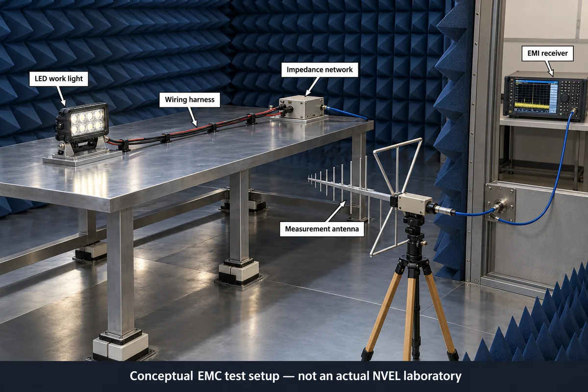
At minimum, the test plan should cover representative supply voltages, full-output mode and relevant dimming states, along with the supplied or specified wiring harness. The applicable limit line must match the test method, detector and frequency band. A peak trace should not be mistaken for a quasi-peak or average result where those detectors are required.
| Verification item | What to request | What the evidence establishes |
|---|---|---|
| Product identity | Model, hardware revision, driver revision and lamp/loom photographs | The report applies to the item being purchased |
| Method and setup | CISPR 25 edition, conducted/radiated method, supply, harness and equipment configuration | The setup is repeatable and relevant to the vehicle |
| Operating modes | Supply voltage, power setting, PWM dimming and load/temperature conditions | The worst relevant normal operating mode was considered |
| Limit and margin | Class, selected band, detector, limit plots and emissions traces | Pass/fail is supported for the stated scope |
| Change control | Engineering change notices and retest triggers | Production changes do not silently invalidate the evidence |
A laboratory’s use of an absorber-lined chamber does not automatically mean the whole fixture passed Class 5. The results must demonstrate compliance with the agreed limits for the actual modes and test scope. For products also requiring radiated immunity, load-dump or electrical-transient resilience, those should be specified and documented under their separate test standards.
Before mass production, suppliers and buyers should agree when a changed PCB layout, driver IC, cable length, enclosure finish or connector requires an EMC impact review and potentially a retest.
5. B2B Sourcing Checklist for EMC-Ready LED Work Lights
Use this checklist in a request for quotation, supplier audit or production approval meeting. Ask for evidence tied to the actual SKU rather than accepting a generic “EMC certified” badge.
- ☐ Define the acceptance target: Specify the CISPR 25 edition, Class 3 or 5 target, test method(s) and relevant receiver bands.
- ☐ Request full test evidence: Obtain conducted and radiated emissions results as applicable, including traces, margins and laboratory identification.
- ☐ Confirm tested configuration: Match the report to the actual lamp, driver revision, harness length, connector and operating modes.
- ☐ Inspect filter and layout controls: Ask how differential/common-mode noise, high-di/dt loops and inductor coupling were assessed.
- ☐ Review installation instructions: Verify intended power wiring, return paths, grounding or isolation rules and cable routing.
- ☐ Separate emissions from immunity: Request ISO 11452 and relevant electrical-transient data only where required by the vehicle program.
- ☐ Check production change control: Agree when BOM, PCB, firmware or harness modifications trigger re-evaluation.
- ☐ Validate the vehicle integration: Plan representative vehicle tests when radios, GNSS or mission-critical fleet electronics are sensitive.
Frequently Asked Questions
Q1. Why can an LED work light create noise on a two-way radio?
A switching LED driver can inject high-frequency current into the shared supply harness or radiate emissions from switching loops, magnetics and wiring. The effect depends on the light, installation and receiver. A conducted/radiated emissions report plus targeted in-vehicle checks can help locate the coupling path.
Q2. What is the practical difference between CISPR 25 Class 3 and Class 5?
For a comparable CISPR 25 measurement and band, Class 5 generally has more stringent disturbance limits than Class 3. The actual numerical limits depend on the standard edition, measurement method, band and detector. A Class 5 claim needs test results for the exact claimed scope; it does not promise zero radio interference.
Q3. Does passing CISPR 25 prove that a light cannot affect CAN-bus or GPS equipment?
No. CISPR 25 is intended to protect on-board radio receivers from disturbances. It can be relevant to GNSS receiver protection, but a passing component result does not guarantee every installation. Digital-network robustness, functional behavior and radiated immunity require their own integration assessments and, where appropriate, separate standards.
Q4. Can EMI filters or shielding reduce brightness?
Filtering and shielding do not inherently require lower light output, but they may add loss, influence converter stability or change thermal behavior. A responsible design verifies both emissions and stabilized optical performance after finalizing the input filter, PCB and housing.
Q5. Is a die-cast aluminum housing enough to meet Class 5?
Not by itself. Shielding effectiveness depends on conductive continuity, seams, lens openings, cable interfaces, bonding and the dominant emissions path. An effective enclosure can complement filtering and layout controls, but only appropriate measurements establish compliance.
Q6. What should an OEM buyer ask NVEL or its manufacturing partners to provide?
Ask for the target market and vehicle program requirements, the specific model and revision, available CISPR 25 test evidence, installation assumptions and a plan for any missing qualification. A supplier’s actual capability, certification and test coverage should be confirmed with current documents rather than inferred from a general product claim.
Conclusion
A reliable EMC plan for industrial and off-road LED lighting starts before the final enclosure is sealed. Driver topology, power filtering, PCB current loops, cable routing and housing interfaces must be treated as one electrical system. Class 3 and Class 5 are useful procurement targets only when their methods, frequency bands and test limits are identified precisely.
For OEM/ODM procurement teams, the practical goal is traceable evidence: an emissions report for the correct lamp configuration, documented operating modes, controlled production changes and vehicle-level validation where needed. Explore relevant LED lighting options or contact the NVEL team to discuss engineering requirements and the documentation available for your project.
Discuss Your LED Work Light EMC Requirements
Explore LED lighting options or contact our OEM team to discuss the test scope and documentation available for your project.