
TECHNICAL GUIDES · OFF-ROAD LIGHTING
Reducing Wind Noise and Thermal Throttling in High-Output LED Light Bars
Engineer airflow, heat transfer and driver protection as one installed system.
October 28, 2026 · Technical Guide
Introduction
Roof-mounted LED light bars are widely specified for overland vehicles, off-road pickups, commercial utility fleets and specialty equipment. Their appeal is straightforward: broad or long-range illumination in a compact package. But a bar that performs well on a laboratory bench can create new problems after installation, especially a narrow-band whistle at road speed and a reduction in light output as the housing heats up.
These complaints originate in different physical systems. Aerodynamic noise depends on the interaction among the light-bar profile, mounting brackets, roof or windshield geometry, and local airflow. Thermal output depends on electrical losses, the LED-to-housing heat path, ambient conditions, and the driver’s protection strategy. Fixing one in isolation can make the other worse: a cosmetic shroud can interrupt airflow, while aggressive fins can change acoustic behavior.
For B2B buyers, an effective LED light bar wind noise fix is therefore not a universal clip or one prescribed mounting angle. It is a documented engineering process: identify the source, compare candidate geometries, measure sound and temperature under representative conditions, and approve a configuration that maintains optical and mechanical performance.
LED Light Bar Noise & Thermal Engineering
QUICK GUIDE
01
Aeroacoustics & Wind Whistling
Identify the installed-system source with repeatable acoustic comparisons.
Compare fin geometry, mounting and cooling together.
03
High-Output Thermal Throttling
Verify sustained output and model-specific driver protection.
04
ADC12 Housings & Thermal Paths
Evaluate the complete heat path and optional thermal technologies.
Define evidence and acceptance criteria before production approval.
1. Why Roof-Mounted Light Bars Whistle
1.1 Distinguishing tonal whistling from broadband wind noise
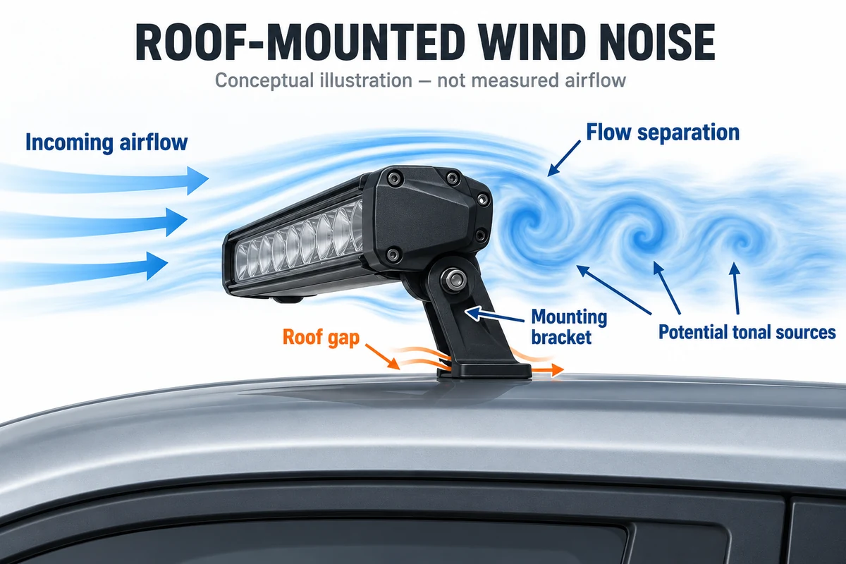
At speed, air moving around a roof-mounted assembly can separate at housing edges, cooling fins, fasteners and brackets. Periodic vortex shedding can generate a tonal sound, while turbulence interacting with the body or windshield may create a broader rushing or buffeting noise. Acoustic resonance can amplify a tone if the flow excitation couples with an installation cavity or structural mode.
Research on vehicle roof bars identifies both vortex-related tonal noise and broadband interaction between roof fittings and the surrounding flow. A light bar is not identical to a roof rack, but the same fluid–structure–acoustic mechanisms provide useful hypotheses for diagnosis. The observed frequency and cabin sound pressure must be measured on the actual vehicle and mounting arrangement; they are not fixed across products.
1.2 Start with the installed system, not the fin profile
A whistle attributed to “the heat-sink fins” may also come from an exposed slot, the gap beneath a mounting bracket, an accessory crossbar, a cable, or a loose trim strip. Record the speed range, crosswind sensitivity, roof rack configuration and changes after the bar is removed or temporarily repositioned. Reversible A/B trials are preferable to permanent drilling or structural changes during diagnosis.
A practical evaluation sequence is to compare the vehicle baseline, vehicle with brackets only, full light-bar installation, and a controlled alternative mounting position. Use repeatable road conditions or a wind tunnel, keeping tyre, vehicle speed and HVAC noise as consistent as possible. Where feasible, use microphone measurements or narrow-band spectral analysis to distinguish a discrete whistle from ordinary background noise.
Wind-Noise Diagnostic Matrix
| Observed symptom | Possible mechanism | Evidence to request |
|---|---|---|
| Whistle begins in a repeatable speed band | Vortex shedding or geometry-dependent acoustic resonance | Speed sweep and narrow-band sound spectrum |
| Noise changes when roof gap or mounting angle changes | Airflow interaction with roof, windshield or bracket | Before/after installation geometry and repeatable A/B test |
| Noise appears with rack/crossbar but not the lamp alone | Accessory interference or trim-related airflow | Baseline, brackets-only and combined-assembly comparisons |
| Buzz or rattle occurs on rough roads | Mechanical looseness, bracket resonance or cable contact | Fastener torque, dynamic check and vibration inspection |
| Higher sound levels appear in crosswinds | Yaw-sensitive separation and flow around edges | Acoustic comparison at different yaw angles |
Buyer takeaway: obtain a test result tied to a defined vehicle or representative fixture, microphone position, mounting configuration, speed range and pass/fail criterion. “Silent at 100 km/h” is not a meaningful universal specification without this context.
2. Fin Geometry, Mounting and Aeroacoustic Trade-Offs
2.1 Why more cooling fins do not automatically mean better design
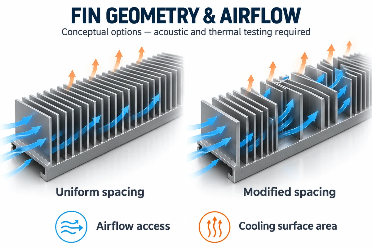
Longitudinal ribs and rear fins can increase exposed surface area, but the effective heat transfer depends on fin spacing, thickness, airflow direction, surrounding obstacles and how heat reaches the fins. Closely spaced fins may reduce usable airflow in some operating conditions. Deep repeated cavities can also create flow features that merit acoustic evaluation.
Candidate approaches include changes to leading-edge shape, fin pitch, gap dimensions, end caps or bracket contours. Nonuniform spacing and carefully selected edge treatments may disrupt coherent flow structures, but they are not guaranteed to eliminate a tone. Each geometry should be compared against a baseline with both acoustic and thermal data. The aim is not the most elaborate fin pattern; it is an acceptable sound signature without sacrificing cooling, manufacturability or cleanability.
2.2 Mechanical isolation is not an acoustic cure-all
Elastomeric pads may reduce transmitted vibration or incidental rattles when specified for the clamp load, temperature and outdoor environment. They do not reliably remove airborne vortex noise generated by the housing. Likewise, third-party fin inserts can change airflow and cooling; they should be approved by the manufacturer before use, rather than treated as a universal accessory.
Mounting height and light-bar tilt may influence the acoustic response, but no single 2–5° adjustment is correct for every vehicle. Changes also affect beam aim, glare risk, legal placement, water exposure, bracket clearance and retention. Any revised installation must be checked against the vehicle and lighting application requirements.
2.3 What to compare during design review
- Acoustic result: tonal peaks and perceived noise over the intended speed and yaw range.
- Thermal result: stabilized case/board temperatures and optical output at specified ambient conditions.
- Installation: bracket stiffness, clearance, cable routing, fastener access and aim stability.
- Durability: vibration, corrosion, water ingress and contamination of fin channels.
- Manufacturing: die-cast/extruded geometry limits, weight and consistent mass-production tolerances.
3. Thermal Throttling: What Buyers Need to Measure
3.1 Separate heat-related LED behavior from electronic foldback
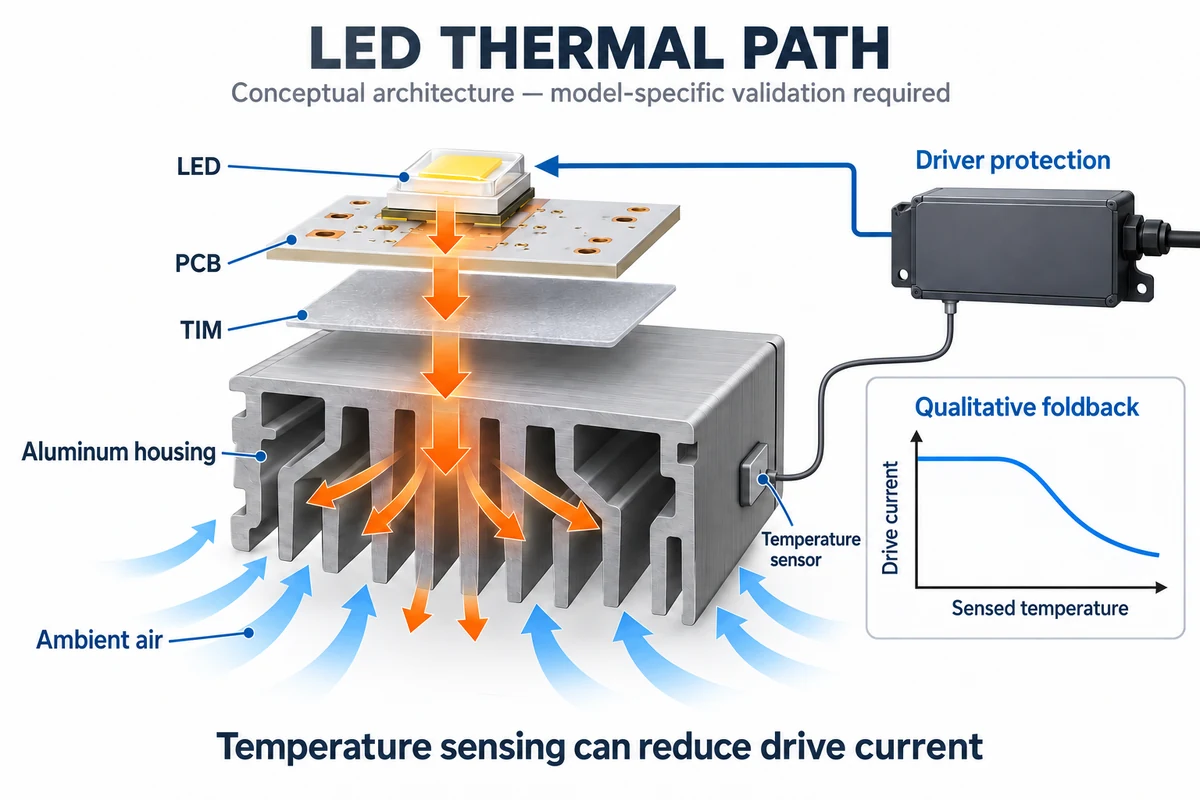
LED systems do not convert all electrical input into useful visible light. A portion becomes heat that must flow away through the package, PCB, thermal interface and housing. As operating temperature rises, LED efficiency and luminous flux can change, even if the driver current stays constant. Separately, a driver with thermal protection may deliberately reduce current to keep critical components within their rated operating limits. These effects should not be described as the same mechanism.
There is no universal junction-temperature threshold of 105°C that triggers every product, and no universal 50% light-output loss. The applicable limits depend on the particular LED data sheet, driver control logic, heat path and ambient-temperature rating. Suppliers should identify the temperature sensing location, foldback initiation point, current-versus-temperature response and recovery behavior for the actual model.
3.2 Design the entire thermal path
The principal heat path is LED junction → package thermal interface → PCB or substrate → thermal-interface material → housing/heatsink → surrounding air. A simplified thermal-resistance model expresses temperature rise as heat dissipated multiplied by effective thermal resistance, but real light bars require allowances for spatial hot spots, interface quality and changes in convection. Orientation and stationary operation are particularly important: a lamp that runs cool at highway speed may run substantially hotter during low-speed crawling, idling or worksite use.
A thermal design review should therefore cover both the worst realistic ambient temperature and the lowest realistic airflow. It should also address supply-voltage range, driver losses, optical output after warm-up, LED board temperature, housing touch temperature where relevant, and repeated thermal cycles. A brief switch-on photograph or “rated 500 W” label is not evidence of sustained output.
3.3 Verify sustained luminous performance
Ask the supplier to measure initial and stabilized light output using a documented electrical and thermal setup. The test duration should be long enough for the product to approach thermal equilibrium; two hours can be a useful customer-defined evaluation period but is not a universal pass criterion. Record input power, current, ambient temperature, case/board temperature and luminous flux at multiple intervals. Where the driver uses foldback, inspect the resulting beam and light-output behavior after the trigger point and after the product cools.
Thermal and Electrical Qualification Matrix
| Test or record | Recommended evidence | Why it matters |
|---|---|---|
| Steady-state thermal test | Ambient, mounting, airflow, voltage, temperature locations and time history | Demonstrates real heat-rejection capacity |
| Luminous output versus time | Initial and warmed-up measured output using the same optical method | Distinguishes sustained output from headline claims |
| Driver thermal foldback | Sensor position, activation logic, current/output curve and recovery | Shows how protection affects illumination |
| Low-airflow / stationary test | Temperature and output with the vehicle stopped or at low airflow | Captures a common hot operating condition |
| Bracket and environmental durability | Vibration, sealing, corrosion and fastener-retention records | Checks that design changes remain mechanically robust |
| EMC assessment where required | Applicable CISPR 25 edition, selected limits, setup, and conducted/radiated results | Helps protect vehicle radio and electronic reception |
4. ADC12, Thermal Interfaces and Optional Heat-Pipe Designs
4.1 Materials must be compared as complete assemblies
ADC12 die-cast aluminum is widely used where a housing needs complex integrated geometry, good casting characteristics and structural features. However, the thermal conductivity of ADC12 is lower than that of high-conductivity wrought aluminum, and published values vary with composition and test method. A material designation alone does not prove the finished assembly has sufficient cooling capacity.
Extruded aluminum can be attractive for long continuous fin profiles, but joints, end caps and sealing interfaces require careful design. Die casting may integrate mounts and cooling structures in fewer parts; extrusion may simplify long linear profiles. The right choice depends on heat load, wall thickness, surface finish, weight, corrosion environment, dimensional tolerances and sealing requirements. Ask for model-specific temperature data rather than relying on a nominal W/m·K material value.
4.2 PCB construction and contact resistance
Metal-core PCBs, direct-thermal-path layouts, copper heat spreaders and carefully selected thermal-interface materials can reduce thermal resistance where properly implemented. Their performance depends on stack-up, dielectric thickness, bonding, clamping pressure, interface voids and how the LED package is mounted. It is not correct to state that every copper-based PCB delivers a fixed 400 W/m·K heat path: bulk material conductivity and effective junction-to-ambient performance are different quantities.
4.3 When heat pipes or vapor chambers are justified
Heat pipes or vapor chambers can redistribute heat from concentrated sources in designs where the packaging space, orientation and reliability requirements support their use. They are optional engineering solutions, not a default feature of high-output light bars. A proposal should include validated operating orientation, vibration retention, thermal cycling and production controls. Additional interfaces can introduce cost and failure modes; the supplier must demonstrate a net system benefit.
A complete thermal review ties the geometry to electrical and optical performance. Fin design, enclosure finish, PCM/thermal-interface selection and driver protection cannot be specified independently if the goal is stable output over a wide environmental range.
5. B2B Sourcing Checklist for High-Output LED Light Bars
For OEM/ODM programs, private-label sourcing and fleet procurement, include the following items in the RFQ and sample-approval plan. Requirements should be proportional to the installation and market; not every product needs every premium material or test.
- Confirm mounting context: roof position, vehicle and crossbar configuration, operating speed range, anticipated yaw and bracket geometry.
- Request repeatable acoustic evidence: baseline-versus-installed measurements, test speed, microphone location and any tonal peak observations.
- Check cooling geometry: fin orientation, flow channels, access for cleaning and the effect of proposed noise treatments on temperature.
- Review thermal data: warmed-up light output, ambient conditions, board/housing temperature, input power and the driver’s actual foldback strategy.
- Verify material and assembly choices: alloy/PCB stack-up, thermal-interface specification, corrosion exposure and manufacturing consistency.
- Assess installation durability: fastener torque, bracket vibration, seals, connector retention, cable strain relief and aiming stability.
- Choose applicable electromagnetic-compatibility requirements for the target vehicle or market; request CISPR 25 evidence when specified, with agreed limits and test configuration.
- Confirm commercial traceability: sample revision, drawings, acceptance criteria, change-control process, warranty terms and matching production BOM.
The strongest supplier proposal is not the one promising zero whistle, 100% constant lumen output or an unverifiable certification badge. It is the one that provides transparent, reproducible evidence for the selected product and installation.
Frequently Asked Questions
Q1. What is the first step in diagnosing LED light bar wind noise?
Identify whether the noise comes from the light bar, its brackets, an existing roof rack or an interacting gap. Document the speed band and installation, then use reversible A/B comparisons. A fin insert or mounting-angle change should only follow an identified cause and a check that beam aim and thermal airflow remain acceptable.
Q2. Why can a light bar become dimmer after warming up?
Temperature can reduce LED optical efficiency, and some drivers deliberately lower current when a sensing threshold is reached. The timing and amount of dimming vary by product. Ask for stabilized light-output measurements, thermal test conditions and the driver’s protection curve rather than assuming a fixed 15–20 minute trigger.
Q3. Can staggered or serrated cooling fins reduce whistling?
Changing fin or edge geometry can disrupt some coherent flow structures and may reduce a tonal acoustic response. Results depend on the complete bar and vehicle installation. Any geometry change should be verified through comparative noise and thermal tests; it is not a guaranteed silence feature.
Q4. Does roof mounting position change wind noise?
Yes. Clearance to the roof, windshield header, crossbar and nearby brackets can change airflow separation and acoustic coupling. Evaluate mounting positions within manufacturer and vehicle limits, and recheck glare, mechanical retention and headlamp alignment after any adjustment.
Q5. Is ADC12 always better than extruded aluminum for light bars?
No. ADC12 supports complex die-cast integration, while extruded profiles can provide efficient long fin geometries. Effective cooling also depends on wall thickness, interfaces, airflow and surface finish. Select the design using complete-assembly thermal data, not alloy name alone.
Q6. What should B2B buyers request from a supplier?
Request an approved drawing and BOM, installation and acoustic test conditions, steady-state thermal and luminous-output curves, mechanical and ingress test evidence, and applicable EMC results. For customized projects, agree on sample acceptance criteria and the process for controlling changes before placing production orders.
Further Reading and Technical References
Lumileds, LUXEON HR30 Application Brief AB217, thermal-management guidance
IEC, CISPR 25:2021 scope and applicability
Conclusion: Engineer Noise and Heat as One System
Reducing roof-mounted LED light bar whistle and limiting unwanted thermal output reduction requires an integrated approach. Airflow geometry, brackets, fin design, electronic protection and heat transfer all affect how the light bar performs after installation. Product comparisons are most credible when sound spectra, temperature traces and measured light output are tied to a documented configuration.
NVEL works with B2B automotive lighting buyers seeking suitable off-road and work-light solutions. Share your vehicle or installation requirements, target market and testing expectations with the NVEL team to discuss product options, sample evaluation and potential customization. Model-specific construction and compliance claims should always be confirmed against the actual quotation and supporting documents.
Explore Automotive LED Lighting Solutions
Explore suitable lighting products or contact the NVEL team with your mounting requirements, operating environment and anticipated order volume.