TECHNICAL GUIDES · EMC & ELECTRICAL DESIGN
Automotive EMC & Electrical Architecture in LED Lighting: Radio Interference and Surge Protection
Understand driver emissions, radio interference, electrical transients and evidence-based B2B qualification.
October 21, 2026 · 14 min read
Introduction
Automotive LED lighting is more than an optical system. Each headlight conversion bulb, fog lamp module or Bi-LED projector also contains an electronic driver that must operate reliably in a vehicle’s demanding electrical environment. For distributors and OEM/ODM buyers, electromagnetic compatibility (EMC) and power-supply robustness are therefore essential parts of product qualification—not optional details to address after complaints appear.
Some installers notice AM/FM radio noise after an LED conversion. Others report intermittent flicker, unexpected dashboard warnings or a driver that fails after a vehicle electrical event. These symptoms can have different causes: switching noise, harness coupling, weak grounding, vehicle lamp diagnostics, power-supply transients or an installation-specific interaction. They should not all be labeled a “CANBus problem,” and no single component can be assumed to resolve every case.
This guide explains how automotive LED drivers produce electrical noise, what CISPR 25 and UN Regulation No. 10 actually address, how transient protection differs from EMI suppression, and what B2B purchasers should ask suppliers to demonstrate before scaling an order.
Automotive EMC & Electrical Architecture
QUICK GUIDE
Switching transitions, current loops and wiring can create conducted and radiated noise.
Emissions testing and regulatory approval have different scopes; verify model-specific evidence.
Qualify the specified electrical profiles and coordinated input-stage protection.
Control noise at its source through layout, filtering, routing and shield bonding.
Review reports, vehicle checks, revision control and traceable production evidence.
1. Where LED Driver Interference Comes From
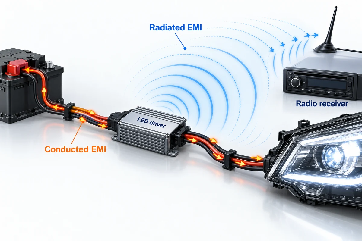
Unlike a simple resistive load, an LED requires controlled current. Automotive LED drivers may use buck, boost or other switching topologies to regulate current across changing supply voltage and operating temperature. Switching frequency, current ripple, component placement and wiring layout all influence the system’s electromagnetic behavior.
Conducted noise and radiated noise
Conducted emissions propagate along electrical conductors, such as vehicle supply and return wiring. Fast current transitions and parasitic inductance can produce voltage disturbances that couple into nearby circuits. Radiated emissions result when switching currents and cable structures create electromagnetic fields that reach receivers or nearby wiring without a direct conductive path.
The path from an LED driver to a radio receiver is not always obvious. A long harness can change the effective radiating structure; connector placement, vehicle grounding, antenna proximity and the driver enclosure can all alter a test result. For that reason, a component-level test is valuable evidence, but an installation or vehicle-level check is often needed before claiming practical compatibility.
Typical symptoms—and what they do not prove
- AM/FM noise appearing only when the lights are on: a useful clue for investigating driver emissions, power wiring, grounding and antenna coupling, but not proof of one particular defect.
- Visible LED flicker: may relate to PWM drive signals, lamp monitoring pulses, insufficient driver input tolerance, wiring faults or thermal behavior; it is not automatically an EMC emissions failure.
- Bulb-out or dashboard warnings: often relate to body control module (BCM) electrical diagnostics and the replacement lamp’s load response. This is a separate compatibility question from radio-frequency emissions.
- Intermittent resets or driver damage: may point to supply disturbance, poor contact, overheating or insufficient electrical protection; the root cause requires testing.
Buyer takeaway: Ask suppliers to distinguish measured emissions performance, vehicle-diagnostic compatibility and electrical transient immunity. These are different specifications.
2. CISPR 25, UN R10 and the Scope of Automotive EMC Evidence
CISPR 25 addresses radio disturbance characteristics associated with vehicles and on-board electrical/electronic components. It establishes measurement approaches for conducted and radiated emissions intended to help protect on-board receivers. The applicable edition, frequency bands, test setup, detector, operating mode and agreed limit line must be stated in any useful laboratory report.
In some test configurations, CISPR 25 defines multiple limit classes. A higher-numbered or more stringent limit may be relevant to a particular customer requirement, but “Class 5” is not a universal guarantee of zero radio static, nor is a generic “CISPR 25 certified” statement a substitute for a traceable report. Results apply to the specific device under test and conditions recorded by the laboratory.
UN Regulation No. 10 (UN R10) concerns the electromagnetic compatibility and applicable approval framework for vehicles and electrical/electronic sub-assemblies. It is not merely another name for CISPR 25. Whether a particular LED lighting product requires an applicable approval, which documentation is needed and what markings may be used must be determined for that product and destination market.
How to read an EMC report
Before accepting “EMC compliant” as a procurement claim, check whether the evidence identifies:
- The exact SKU, driver hardware and firmware revision, cable set and test sample configuration.
- The standard and edition, measurement method, limit class where applicable, and operating modes assessed.
- Conducted and radiated emissions results, including frequency-dependent margins and any deviations.
- The laboratory, report number, date and scope of testing.
- Whether a separate regulatory approval is actually required and documented for the intended sale or installation.
A convincing engineering dossier may include both laboratory emissions results and vehicle-fitment or installation trials. Neither should be presented as a blanket promise that every possible vehicle and radio receiver will perform identically.
3. Electrical Transients, Load Dump and LED Driver Protection
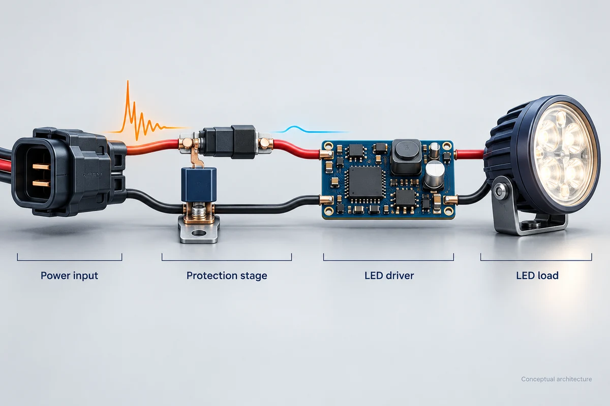
A vehicle electrical system does not supply perfectly constant DC power. Cranking, changing electrical loads, switching inductive devices, wiring errors and charging-system events can create voltage dips, reverse connections or transient overvoltage. These issues concern electrical robustness and immunity, not simply the radiated-emission level measured under CISPR 25.
ISO 7637-2 provides test methods for certain conducted electrical transients along vehicle supply lines. ISO 16750-2 addresses a broader set of electrical loads and operating conditions, including relevant overvoltage, supply interruption and load-dump considerations. The required tests and acceptance criteria depend on the vehicle platform, supply system, equipment function and customer specification.
Electrical risks and possible design responses
| Risk or condition | What buyers should evaluate | Possible engineering response |
|---|---|---|
| Supply-line transient pulses | Applicable pulse profile and post-test functionality | Appropriately selected transient suppression and input protection |
| Load-dump event | Specified voltage/time profile for the target vehicle system | Coordinated TVS, active clamping and/or driver input-stage protection |
| Reverse battery connection | Polarity and duration requirements | Reverse-polarity MOSFET or diode protection |
| Cranking and supply dips | Minimum supply conditions and lamp behavior | Input undervoltage strategy and suitable driver regulation |
| PWM or lamp-diagnostic pulses | Actual vehicle waveform and flicker behavior | Validated driver input response and, where appropriate, filtering |
| High operating temperature | Temperature rise, derating and thermal shutdown behavior | Thermal design, current derating and protection controls |
A transient voltage suppressor (TVS) diode can help clamp specified electrical surges when correctly selected and coordinated with the surrounding circuit. However, it is not a universal fix for radio interference, and its presence alone does not prove survival of every load-dump event. Likewise, an LC filter intended to reduce conducted noise cannot be assumed to solve an unrelated reverse-polarity or thermal problem.
Buyer takeaway: Request the exact electrical test profile and the observed functional result—not just a diagram showing a protection diode.
4. Practical EMI Reduction: PCB Layout, Filtering and Shielding
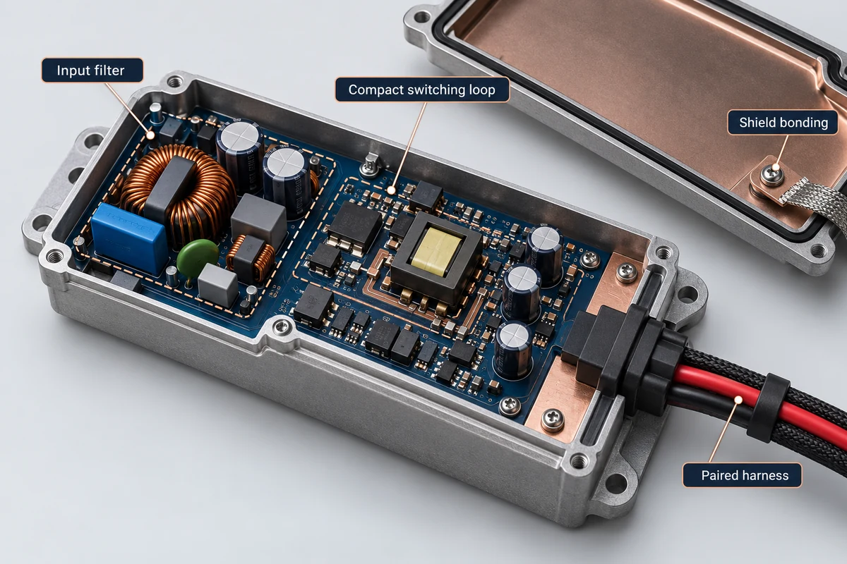
Strong EMC performance usually comes from a coordinated design process rather than a single “anti-interference” accessory. Engineers need to control noise at its source, limit coupling pathways and verify the outcome in the intended installation.
Switching and PCB layout
Reducing high-current switching-loop area, choosing suitable driver components, placing bypass capacitors appropriately and managing return-current paths can materially affect emissions. Component selection should be assessed together with the PCB design, not in isolation.
Input filtering and common-mode control
An input LC network may help attenuate differential-mode noise; common-mode chokes or ferrite components can help with other coupling paths when chosen for the relevant impedance and frequency behavior. Filter effectiveness depends on source and load impedance, placement and cable routing. Poorly applied filtering can introduce undesirable resonance or change power-up behavior.
Cable routing and shielding
Shielded cables, conductive enclosures and appropriate grounding strategies may reduce coupling under certain conditions. An aluminum enclosure is not automatically an effective Faraday cage: seams, connectors, cable exits, bonding and shielding termination matter. Equally, an external snap-on ferrite can be a useful troubleshooting aid but is not evidence that the underlying driver has passed a specified EMC test.
Validate the finished system
A useful engineering workflow is to measure a representative driver and harness combination in different operating modes, review results against the intended limit, refine the design and then repeat the test. Production controls should track meaningful changes to the driver IC, PCB, cable, enclosure or LED load, because those changes may affect emissions and transient response.
For aftermarket products, representative in-vehicle checks can help discover installation-specific issues. They complement laboratory evidence; they do not replace it where regulatory or contractual requirements apply.
5. B2B Quality Checklist for Automotive EMC LED Lighting
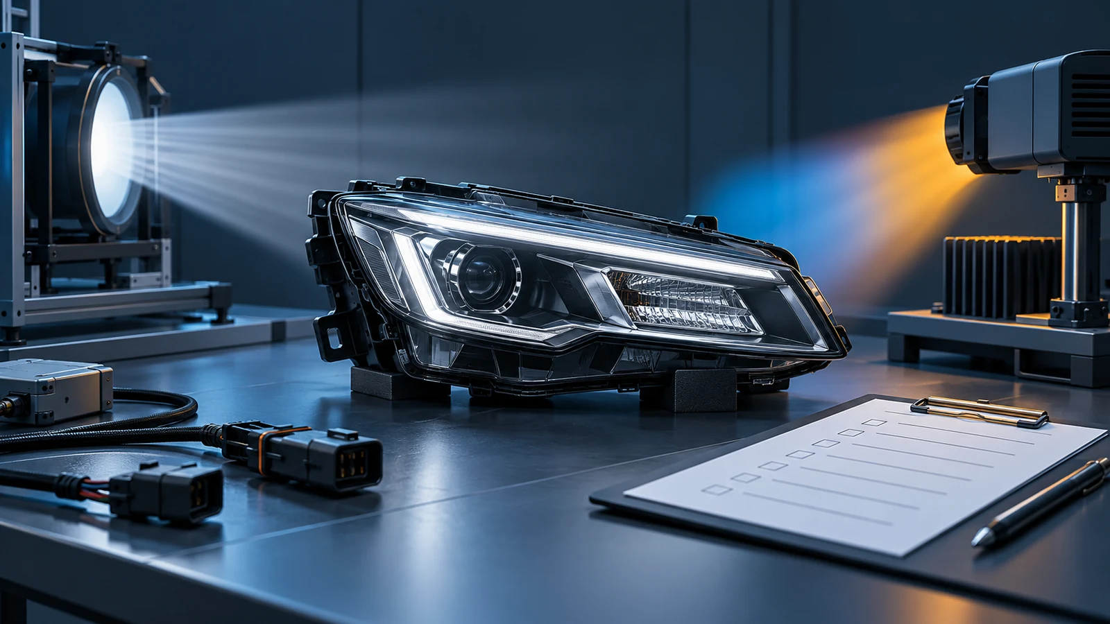
Automotive lighting buyers need repeatable evidence at the exact SKU level. Use the following checklist when reviewing samples, comparing quotations or approving a supplier for repeat orders.
- ☐ Define the application. Record vehicle supply voltage, lamp location, driver type, installation harness, expected operating modes and target markets.
- ☐ Request emissions evidence. Ask for a traceable CISPR 25 report, including edition, actual measured results, applicable limits, cable configuration and product revision.
- ☐ Check applicable regulatory status. Where UN R10 or other approval is required, request the actual model-specific approval documents and confirm relevance to the destination market.
- ☐ Review electrical robustness. Request test conditions and outcomes relevant to ISO 7637-2, ISO 16750-2 or the buyer’s specified automotive transient profiles.
- ☐ Assess radio-interference symptoms. In representative installations, check multiple radio bands and operating modes using a consistent, documented procedure.
- ☐ Separate BCM diagnostics from EMC. Test bulb-out warnings and PWM flicker on relevant vehicles rather than claiming universal “CANBus error-free” fitment.
- ☐ Review thermal and component control. Ask how the supplier validates hot operation, protective derating, PCB revision control and driver substitution.
- ☐ Confirm traceability and change notification. Require SKU, hardware revision, test-report mapping, lot identification and notice before material component changes.
- ☐ Align packaging claims with evidence. Allow “CISPR 25 tested” or specific approval statements only when documentation genuinely supports that wording.
- ☐ Agree on field-issue handling. Define sample-retention, return analysis, corrective-action expectations and acceptance criteria for future orders.
Minimum supplier evidence matrix
| Procurement question | Evidence to request | Red flag |
|---|---|---|
| Will the driver disturb in-vehicle receivers? | Model-specific conducted/radiated emissions data and operating conditions | A generic “zero EMI” promise without a report |
| Can it tolerate vehicle electrical events? | Defined electrical transient and supply-voltage test results | “TVS equipped” with no test profile |
| Will dashboard warnings or flicker occur? | Vehicle- or platform-specific diagnostic compatibility checks | “Fits every CANBus vehicle” |
| Does a regulatory approval apply? | Authentic approval number/document for the correct unit | Unverified E-mark artwork or copied certificate |
| Will repeated shipments remain equivalent? | Revision-controlled BOM, QC records and change-control process | Unannounced substitution of driver electronics |
6. Frequently Asked Questions
Q1. Why can LED headlight conversions create AM or FM radio noise?
A switching LED driver can generate conducted or radiated electromagnetic noise. Depending on harness geometry, grounding, antenna location and filtering, some of that noise may couple into a vehicle receiver. Diagnosis should include the complete installation rather than assuming that every radio-noise complaint has the same root cause.
Q2. Does passing CISPR 25 Class 5 guarantee interference-free operation?
No. CISPR 25 results describe measured emissions against specified limits under defined test conditions. A stringent class can be valuable, but it does not establish zero emissions or guarantee compatibility with every receiver and vehicle configuration. Ask for the exact report and its scope.
Q3. Are CISPR 25 and UN R10 the same requirement?
No. CISPR 25 provides methods and limits associated with protecting on-board receivers from radio disturbance. UN R10 is a regulatory EMC framework for vehicles and applicable electrical/electronic sub-assemblies. Product scope, required approval and supporting documentation should be checked separately.
Q4. What is a load-dump event, and can a TVS diode prevent all damage?
Load dump is a charging-system electrical event that can produce a substantial supply overvoltage under particular conditions. TVS devices and other coordinated input protections may help a driver withstand the specified waveform, but the correct selection and actual test result matter. One diode is not a guarantee against all electrical faults.
Q5. Can a snap-on ferrite fix LED-induced radio interference?
Sometimes it helps reduce a particular high-frequency coupling path. Results depend on material, placement, frequency, cable current and the dominant noise mechanism. If the driver layout or input filtering is inadequate, a ferrite alone may not resolve the issue. It should be treated as a diagnostic or design option, not a substitute for testing.
Q6. Is “CANBus compatible” the same as EMC compliant?
No. “CANBus compatible” is often used in the aftermarket to describe lamp-diagnostic behavior, even though many replacement bulbs are not directly connected to the vehicle CAN network. EMC concerns unwanted electromagnetic emissions and susceptibility. Both need application-specific validation.
Q7. What should NVEL distributors ask for before a bulk order?
Request the relevant model’s driver specifications, available emissions and electrical-load test records, applicable approvals if required, sample-fitment information, lot traceability and change-control arrangements. Specific claims about NVEL testing capabilities, accreditations or product approvals should be made only when documentary evidence is available for the referenced SKU.
Conclusion: Design Evidence Is More Valuable Than “Zero-Interference” Claims
Reliable automotive LED lighting combines optical performance with well-designed electronics. Controlled switching loops, suitable filtering and shielding, robust power-input protection, documented test conditions and careful vehicle application checks can help reduce radio-interference complaints and improve product reliability. None of these measures should be marketed as a universal guarantee without matching evidence.
For distributors and OEM/ODM buyers, the most effective sourcing approach is to qualify the exact product configuration, review supplier documentation and agree on transparent acceptance criteria before scaling orders. NVEL can discuss application requirements and available model-specific documentation for potential automotive lighting programs.
Explore NVEL Automotive LED Lighting Products
Share your target vehicles or market, lighting category, electrical supply requirements, expected order quantity and any EMC or electrical protection test specifications. The NVEL team can help review suitable product options and the documentation available for evaluation.
Technical and regulatory note: This guide is general engineering and sourcing information. Product-level compatibility, emissions, electrical-transient performance and regulatory approval must be verified for the specific configuration, destination market and installation.