TECHNICAL GUIDES · LED HEADLIGHTS
H4 LED Headlight Bulb Engineering: Dual-Beam Switching, Fitment & OEM Validation
Dual-beam switching, optical fitment and traceable OEM sample approval.
November 5, 2026 · 15 min read
Introduction
An H4 LED headlight bulb faces a two-function engineering problem: a single replaceable source is expected to support both low-beam and high-beam operation inside an existing headlamp. A product that fits the H4 socket or changes modes on a bench is not automatically a suitable replacement. Both beam functions must be evaluated in the headlamp and electrical environment for which the product is proposed.
The original H4 halogen arrangement uses different filament locations and light-control features for its two functions. An LED design can use separately controlled emitter regions, current modes or another defined architecture, but its optical output is governed by the final source geometry, seating, driver behavior and headlamp reflector. A white-looking cutoff and a working high-beam indicator are only initial observations—not a complete validation.
This Technical Guide focuses on H4-specific low/high switching, optical registration, compact installation and OEM approval evidence. For basic H4, H7, H11, HB3 and HB4 type comparisons, see NVEL’s bulb-type guide; for general retrofit optics, see its LED beam-pattern engineering overview. Those subjects are intentionally not repeated here.
Table of Contents
H4 LED Engineering Quick Guide
QUICK GUIDE
Define the two optical functions and the H4 source architecture.
Verify driver commands, transitions and diagnostic behavior.
Check source position, locking and rear housing clearance.
Measure each beam after thermal stabilization.
Tie evidence, BOM and revision control to the golden sample.
H4 LED Headlight Bulb Architecture: One Bulb, Two Beam Functions
The H4 designation describes an established dual-function replaceable halogen source family. In the conventional design, two filaments serve distinct optical functions through different locations and shields. The headlamp has been engineered to collect their light in different ways. A drop-in LED H4 replacement must therefore be assessed as a source-and-headlamp combination, rather than as a bulb with a marketing claim of two output levels.
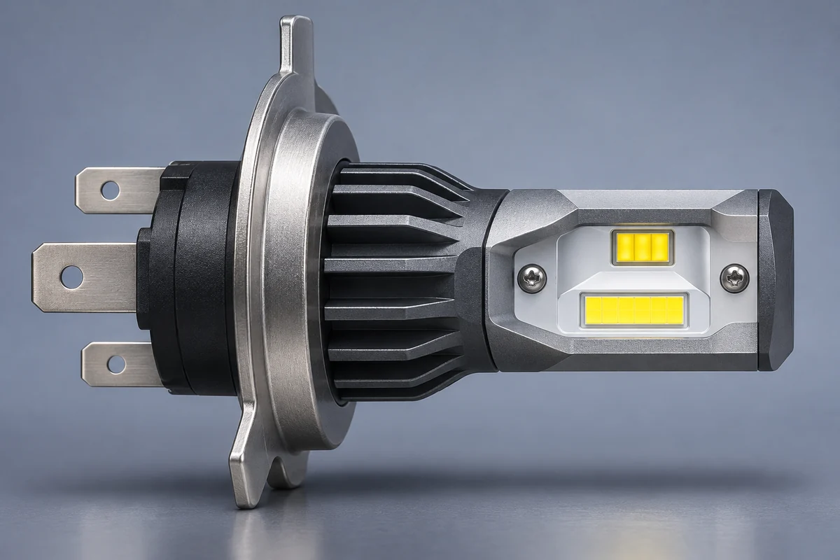
Use the original two-filament behavior as a reference, not a literal LED blueprint
For a representative halogen headlamp, record what changes when the low-beam command is replaced by the high-beam command: useful distribution, cutoff behavior, forward intensity and any additional illuminated regions. The exact reference is the applicable headlamp and original source—not an arbitrary wall photograph. The specification should describe the intended low and high functions and the regulatory conditions of the destination market.
H4/9003/HB2 terminology may overlap in catalogs, but a label alone cannot establish identical approvals, vehicle fitment or electrical behavior. Do not reshape locating tabs, force a retaining spring or assume that a base described as P43t resolves every dimensional and optical requirement. The existing NVEL H4 bulb-type comparison covers the naming background.
Identify the LED emitter and driver architecture of the exact SKU
An H4 LED product may switch between emitter zones, use different drive states, or employ a design-specific optical arrangement. The buyer needs a controlled drawing and electrical description showing which light-producing elements are active in each commanded mode. Catalogs may reverse the term to LED H4; this shorthand does not establish fitment or approval. Avoid prescribing a universal board, chip count, beam angle or mechanical shutter: designs vary, and only the validated final configuration determines performance.
Record both the driver implementation and the connector interface. A compact integrated driver can simplify package routing, while an external driver adds harness and mounting requirements. Neither architecture is automatically better. What matters is repeatable mode response, supply tolerance, thermal stability and the installed optical result.
Define unambiguous low/high operating states
An H4-type connection normally has a common terminal and separate circuits for the two beam commands, but the actual vehicle-side wiring, ground strategy and diagnostics must be verified. Do not assign a universal wire color, pin orientation or polarity from a generic diagram. The engineering document should specify the test fixture, supply, input state, response and unacceptable combinations.
H4 Dual-Beam Function-State Verification Matrix
| Input / test state | Expected product behavior | Evidence / failure check |
|---|---|---|
| Low-beam command only | Specified low-beam operating mode; stable electrical input and output | Record current and mode response; assess complete low-beam distribution |
| High-beam command only | Specified high-beam operating mode; correct intended intensity distribution | Record driver response and complete high-beam photometry |
| Transition low to high and back | Repeatable switching without unintended dark intervals or persistent wrong mode | Cycle the switch under defined supply and thermal conditions |
| Vehicle warning / PWM condition where applicable | No unapproved flicker, warning or unsafe thermal response | Test on representative vehicle/control architecture |
| Power interruption / restart | Defined startup state and recovery behavior | Record restart at stated ambient, voltage and warm conditions |
The table is an OEM test-plan example, not a claimed result for any NVEL model. Set pass/fail limits and test methods before the supplier submits samples.
Low- and High-Beam Switching: Electrical Control and Failure Modes
An H4 LED headlight replacement can pass a short bench demonstration and still fail in a real vehicle. The driver may respond differently to voltage dips, PWM control, lamp monitoring or transitions between beam commands. The correct validation unit is the exact bulb SKU, its associated electronic parts and the representative vehicle headlamp circuit.
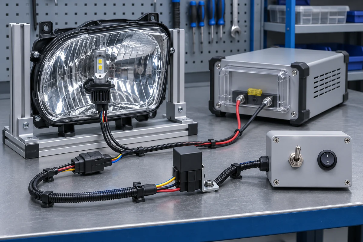
Test mode transitions across the operating envelope
Begin with the approved electrical schematic and supported voltage range. Measure steady and transient input behavior in low beam and high beam separately, then switch repeatedly after thermal stabilization. Include cold start, warm restart, interruption and applicable vehicle diagnostic pulses. The acceptance plan should specify whether the design permits any intentional overlap, delay or fallback state, rather than guessing what a “normal” switch should look like.
Some vehicles monitor filament load or modulate the supply. A product labeled CANbus-ready may still trigger a fault on a specific platform; the communications network and lamp-out monitoring are not synonymous. An external decoder or resistor is not a universal fix and may create additional heat, wiring or EMC concerns. Verify the complete installed system, and specify accessories only for applications where evidence supports them.
Separate electrical faults from optical defects
H4 Electrical and Optical Troubleshooting Matrix
| Observed symptom | Possible cause to investigate | Required confirmation |
|---|---|---|
| Low beam works, high beam does not | Input mapping, driver state or emitter group fault | Connector trace and commanded-state measurement |
| Both modes illuminate but road pattern hardly changes | Source architecture, mode control or unsuitable headlamp optics | Independent low/high photometric distribution tests |
| Intermittent switching or flicker | PWM, diagnostic pulses, supply drop or connection resistance | Voltage/current waveform with test condition |
| Warning lamp or lamp-out diagnostic | Vehicle monitoring incompatible with installed current behavior | Vehicle-specific diagnostic and accessory verification |
| Output weakens after warm-up | Driver thermal foldback or insufficient cooling envelope | Stabilized output and component-temperature record |
Do not decide from the symptom alone that the LED bulb is defective. A changed optical pattern can be caused by seating, the headlamp design or the source itself; an electrical warning can arise from control logic rather than a failed emitter. Keep diagnosis and corrective action traceable to the precise configuration.
H4 LED Fitment: Emitter Position, Base Alignment and Housing Clearance
An H4 LED replacement inherits the existing reflector or projector assembly, whose optical surfaces were designed around a specific source geometry. Even small shifts in the luminous area, angular orientation or seating datum can change which areas of the reflector receive light. Unlike a dedicated headlamp redesign, a bulb-only change cannot assume control of the entire optical path.
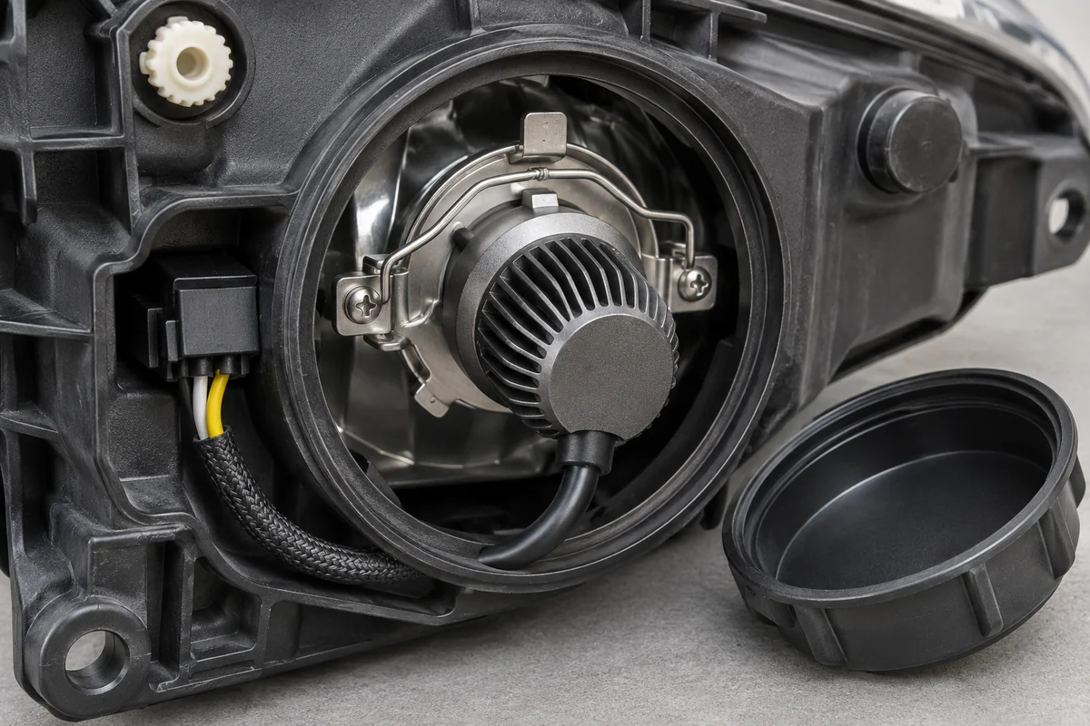
Control source registration and retaining geometry
Review the mechanical datum on the H4 base, the actual locating-tab engagement, retainer preload and whether the bulb can rock or rotate after locking. Source position is three-dimensional: axial offset, radial offset, orientation and emitting-surface extent all matter. For a replaceable LED design, document its emitter surfaces relative to the mounting reference and tie the drawing revision to the sample under test.
A bulb with an adjustable collar requires a controlled setting and a way to reproduce that setting across production. A technician’s subjective rotation to make one wall photograph look attractive is not a qualified process. Compare measured beam distributions from several representative lamps in the intended headlamp and assess the sensitivity to permitted assembly tolerances.
Check the complete installed package, not just nominal bulb length
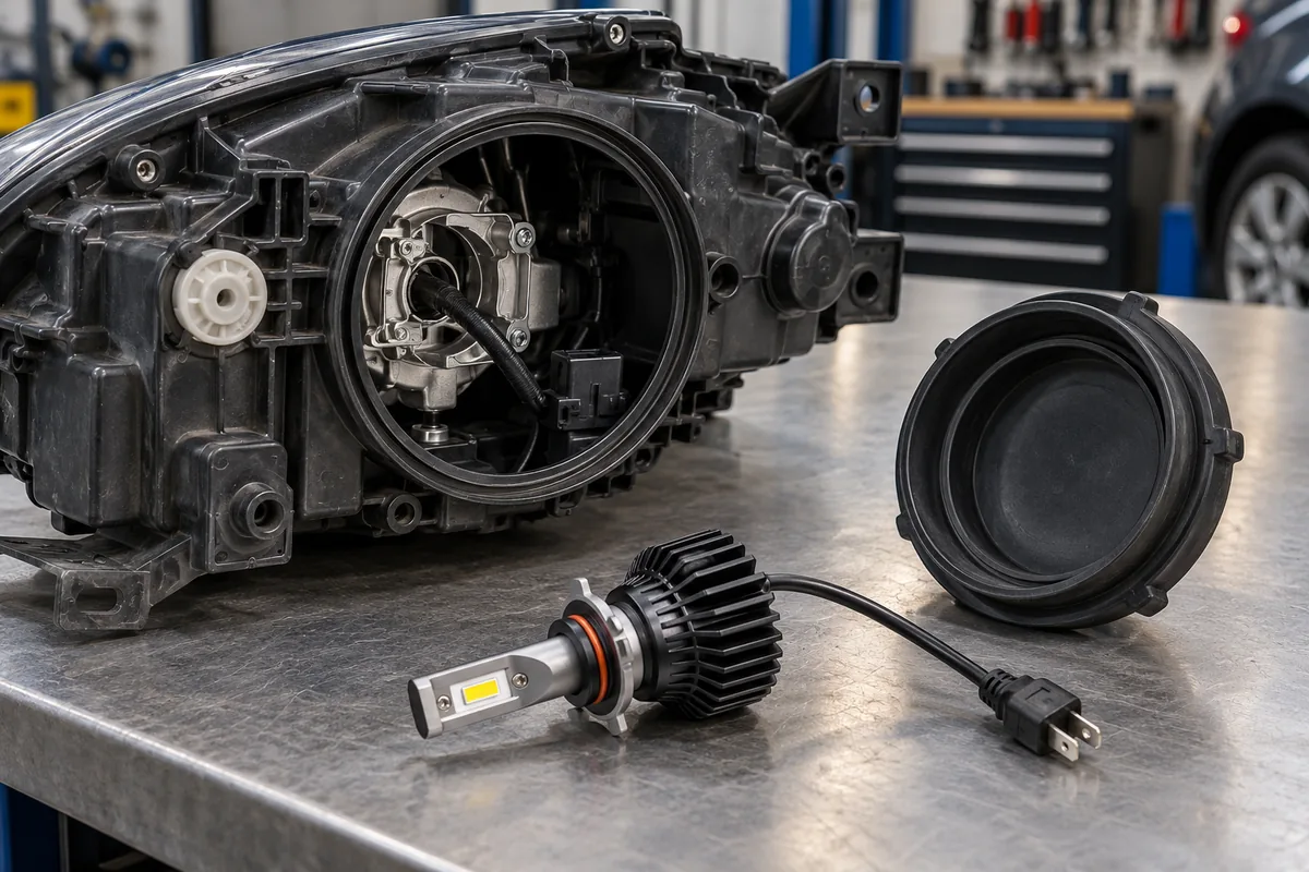
Measure the required rear envelope after the bulb is fully seated: cooling fan or heat sink, integrated or external driver, cable bend radius, connector, dust cover and any retainer or adapter. Confirm the rear cover closes without compressing the cable or blocking necessary airflow. Evaluate service access, water sealing and the effects of dust, vibration and temperature in the intended orientation.
If a product is advertised as plug and play, document the exact supported lamp assembly and installation parts. Do not trim the lamp housing, distort a cover or remove a seal merely to make a sample fit. Any change to the original optical system or enclosure requires its own technical and regulatory assessment.
H4 Installation and Optical Registration Checklist
| Review item | Document / measurement | Acceptance focus |
|---|---|---|
| Base and retaining system | Keying, seating depth, retainer drawing and locking check | Correct datum and no unintended movement |
| Emitter position / orientation | Revision-controlled LED-source drawing and assembled sample | Repeatable alignment to approved test assembly |
| Rear packaging | Fan or heatsink clearance, cover space and cable route | No interference or seal damage |
| Cooling path | Ambient, installed orientation and cover condition | Stable operation without blocked airflow |
| Mechanical durability | Defined vibration / handling sequence and post-test check | Retention, wiring and optical alignment remain acceptable |
Validating H4 LED Performance: Two Beams, Thermal Stability and Road-Use Scope
Low beam and high beam serve different purposes, so they need separate acceptance evidence. A successful electrical switch is not evidence of a compliant low-beam cutoff or useful high-beam range. A single maximum-lumen claim is also insufficient because lumens do not describe where light is sent. The relevant result is the completed bulb-plus-headlamp optical distribution under recorded operating conditions.
Measure each beam in the same representative assembly
For low beam, examine the appropriate distribution, regions sensitive to upward stray light, forward coverage and uniformity using an agreed test method. For high beam, evaluate the intended forward intensity distribution and the transition from low to high; do not infer it from chip wattage. If the market requires a specified photometric procedure, test the exact submitted configuration under those conditions rather than inventing a universal lux or candela threshold.
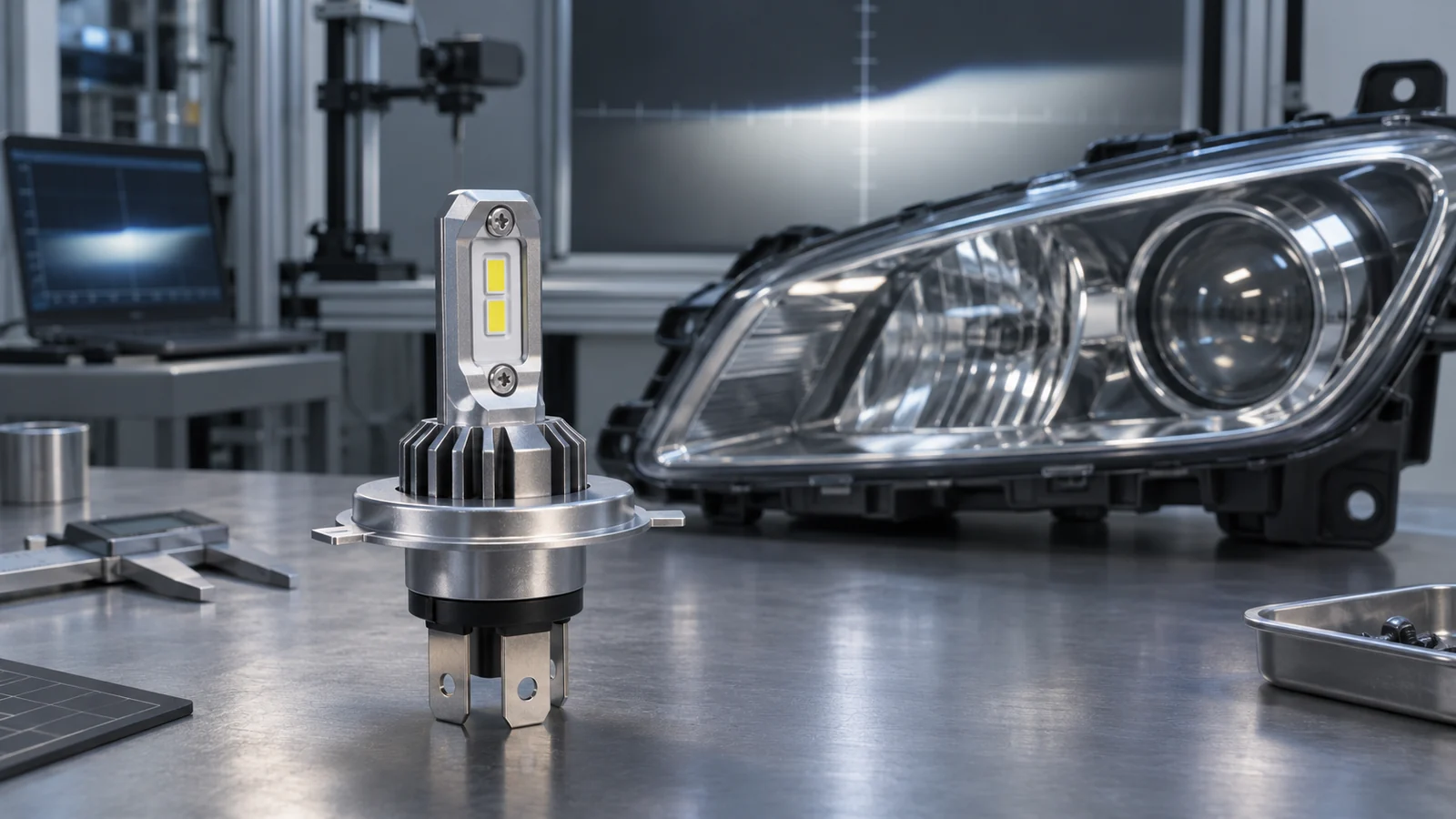
Record headlamp part number, aiming method, supply voltage, instrument or test fixture, sample revision, ambient conditions, thermal stabilization and measurement date. Compare more than one sample when drawing conclusions about production. For general source-geometry and glare background, NVEL already explains why the beam pattern changes after an LED upgrade. This guide instead defines the H4-specific evidence needed for both beam functions.
Treat stabilized output and legal approval as distinct checks
Check the bulb after a documented warm-up period in the intended enclosure. Assess whether thermal behavior changes input current, emitter intensity, beam balance or switching reliability. A short open-air demonstration does not establish installed stability or service life; any lifetime, IP, EMC or temperature claim should be tied to evidence for the tested model and method.
Road-use status cannot be inferred from an H4-shaped base. In its February 13, 2024 interpretation, the US National Highway Traffic Safety Administration explains that integral LED headlamps and LED replacements for standardized replaceable-bulb headlamps are treated differently under FMVSS No. 108. That letter does not establish blanket permission for H4 LED replacement bulbs in US public-road headlamps. See the NHTSA interpretation.
Other markets may approve defined LED retrofit products for specific vehicles, headlamp approval numbers and light functions. For example, OSRAM’s NIGHT BREAKER LED compatibility guidance instructs users to verify the relevant vehicle and headlamp before relying on an approval. Those approvals cannot be transferred to an unrelated NVEL product. Review the precise destination-market rules, product documents, vehicle installation and authorized light functions before making a road-legal claim.
OEM H4 LED Headlight Bulb Sample Approval and Production Control
For a distributor or private-label brand, accepting an H4 LED sample is a controlled engineering decision, not a choice based on appearance or a brief on/off test. A signed-off sample should be linked to the exact bill of materials, LED package, emitter-board dimensions, driver revision, thermal assembly, base, packaging contents and approved vehicle/headlamp application. Define the commercial SKU and any accessory SKU independently.
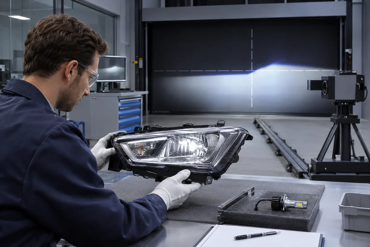
Turn the H4 dual-beam requirements into an RFQ
An RFQ should request the supplier’s two-mode input and output descriptions, connector diagram, dimensional assembly drawing, measured low/high photometry for the nominated headlamp and stabilized electrical/thermal test conditions. Include adapter or decoder details only if the target application actually requires them. Require any claimed certification or approval to identify the exact scope and model revision.
As a real NVEL product-family reference, the O1 Mini LED Headlight Bulb Kit lists H4 among its available socket configurations, an integrated driver and distinct nominal low-/high-beam power ratings. These are published product specifications, not independent road-approval or model-fitment evidence. Obtain current drawings and sample test reports before applying the O1 configuration to an OEM program.
Use a golden sample and control every optical or electrical revision
Approve representative samples only after recording the tests and deviations. Keep a golden sample with the same identified revision, and evaluate production samples against the approved tolerance range. Changes to emitter placement, driver current, PCB thickness, collar position, cooling structure or firmware-like control behavior can affect both modes and may require repeat electrical and photometric validation.
OEM H4 LED Sample Approval and Change-Control Matrix
| Approval gate | Evidence to request | Decision / revision control |
|---|---|---|
| SKU and BOM | Exact H4 variant, driver, connectors, cooling and accessories | Match commercial model, drawings and golden sample |
| Low/high electrical function | Mode-state matrix, input traces and vehicle diagnostic results | Pass each function and transition at agreed conditions |
| Installed photometry | Low-beam and high-beam distributions in identified headlamp | Accept against applicable project/market criteria |
| Mechanical / thermal | Dimensional checks, enclosure clearance, stabilized operation | Record orientation, supply, ambient and results |
| Durability and EMC | Application-specific test protocols and genuine reports | No unsupported blanket pass or certification |
| Change control / production | BOM revision, sample IDs, process checks, deviation log | Requalification triggers and lot traceability defined |
Do not accept an unsupported “universal H4 fitment” statement in place of application data. A compact installation design, a stable low/high control system and traceable test evidence together form a stronger basis for an OEM purchasing decision than nominal power or brightness figures alone.
- Confirm the exact H4 SKU and all included or required accessories before ordering.
- Approve both low-beam and high-beam switching states on the intended circuit.
- Review separate low- and high-beam photometric results for the actual headlamp.
- Verify base registration, locking, rear-cover clearance and cooling path.
- Document thermal, vibration, EMC and electrical checks appropriate to the project.
- Confirm road-use approval only where valid documents cover the precise application.
- Record golden sample, BOM revision, acceptance criteria and production re-test triggers.
Frequently Asked Questions
Does an H4 LED headlight bulb provide both low beam and high beam?
An H4 LED replacement is commonly marketed for dual-function headlamps, but its actual two-mode behavior depends on the specified design and wiring. Verify both commands and the resulting light distributions in the particular headlamp; the H4 label alone does not prove the outcome.
Are H4, 9003 and HB2 LED headlight bulbs always interchangeable?
These designations are often cross-referenced in catalogs, but that does not guarantee identical electrical characteristics, mechanical tolerances, market approvals or vehicle compatibility for every LED product. Verify the exact application documents instead of relying on names alone.
Why can low beam look acceptable while H4 LED high beam performs poorly?
The LED source position, mode-control architecture and interaction with the headlamp optics can affect the two distributions differently. A clear-looking low-beam boundary does not predict high-beam coverage. Measure both functions with the same identified assembly and operating conditions.
Can an H4 LED bulb fit the socket yet still be unsuitable?
Yes. Correct keying does not establish correct optical registration, clearance, cooling, diagnostics or road-use approval. Examine the installed headlamp system and test the exact bulb configuration rather than using a socket-fit claim as the acceptance criterion.
Are H4 LED replacement bulbs legal for use on public roads?
Approval depends on the product, vehicle, headlamp and jurisdiction. US replaceable-bulb headlamps face specific FMVSS 108 constraints, while certain European retrofit LED products have limited application-specific approvals. Do not generalize a competitor’s or another country’s approval to a different H4 LED bulb.
What should an OEM buyer request before accepting H4 LED samples?
Request the exact BOM and revision, source-geometry drawings, low/high input and output records, separate photometry, thermal and mechanical test conditions, supported applications, applicable approval evidence and a documented production change-control plan.
Conclusion
An H4 LED headlight bulb should be judged as a two-mode light source operating within a specified headlamp—not simply as a brighter H4-shaped part. The engineering challenge is to preserve reliable low/high electrical control and achieve useful, controlled optical distributions after the lamp is fully assembled and installed.
For OEM and B2B projects, define the intended application, verify both beam functions independently, document the mechanical and thermal envelope, and approve only a traceable sample revision. That approach reduces ambiguous compatibility claims and makes production decisions more defensible.
Plan Your H4 LED OEM Validation
Explore automotive LED lighting options or discuss your target headlamp, switching requirements and sample approval plan with our OEM team.